Announcement

Collapse
No announcement yet.

Manipulating Of Magnetic Flux

Collapse
X
 
  • Filter
  • Time
  • Show
Clear All
new posts

  • #46
    Originally posted by broli View Post
    You should stick to the iron piece.
    Hi Broli,

    If you answered to me that, would you mind giving some more explanation, you lost me... sorry.

    Thanks, Gyula
    Comment


    • #47
      Originally posted by gyula View Post
      Hi Broli,

      If you answered to me that, would you mind giving some more explanation, you lost me... sorry.

      Thanks, Gyula
      I mentioned it to pardox's last animation. The last idea has more complex interactions especially when adding a coil to it. But as far as I can tell it has no advantages over figure 4.

      I believe we should stick with the setups that have the moving iron. Iron is a very interesting material as its magnetic elastic and can be magnetized in any direction, that property is lost when using PM's only.

      The reason why I prefer figure 2 the most is that it's a very simple and near solid state setup. You only have the iron moving/rotating while the rest is stationary. With springs things might become hard, tuning and building wise. While figure 2 only needs a rotor with an iron piece, a stationary coil and a stationary magnet.

      There are some setups online that are close to this concept. Like the shown above by DQuale. Lindemann for instance also uses magnetic attraction to cause the iron rotor to rotate. But it's not self energized as the coil is provided with power (which gets recycled) and uses no PM's. Flynn's Parallel Path principle device on the other hand does use PM's for the attraction part but still uses energized coils to change the flux path. Naudin has numerous other concepts on his website which are similar.

      But none work in exactly the same way as mentioned above. If my assumption is correct it would be self accelerating and self energizing. Almost like Thane Hein'ss perpeteia which is self accelerating ONLY above a certain RPM. But again using a slightly different method.

      The next phase is to build it and experiment with it.
      Last edited by broli; 07-18-2009, 11:31 AM.

      Comment


      • #48
        I think that was the answer to my possible enhancements of figure 4

        Gyula, in your case I feel it would be better to use a coil with a ferrous core because those types of coils tend to be much more potent. Even if it did change the behavior of the iron piece, it would apply on the journey there, but also the same when moving the piece away since the system is symmetrical. If the system stays truly symmetrical then the resultant "drag" will always be 0 because where you lose on the one half you gain on the other.

        Comment


        • #49
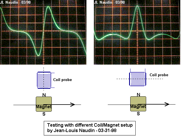
          Here are some scope shots that show the voltage in the coils at an approaching magnet.


          They are taken from an experiment to an unrelated motor jnaudin was working on.

          The scope shot that is of interest is the left one. Which shows the behavior I described earlier. When iron (magnet in image) hits TDC the voltage is zero. This is when we shut off the coil. And leave only the magnet attracting the iron piece.

          Here is the behavior in our case:

          Last edited by broli; 07-18-2009, 12:07 PM.

          Comment


          • #50
            Originally posted by broli View Post
            The next phase is to build it and experiment with it.
            Yes definitely!
            I will be playing with a few possible designs in CAD today, my main goal keeping everything as simple and solid-state as possible, while keeping the flux gating mechanism mechanical, like a perforated iron disc. When the flux gating mechanism is a coil, things become very complicated because your pickup coil can end up leaching from your gating coil, like in the MEG and who knows what that will do to efficiency.

            Comment


            • #51
              @broli

              Thanks for your kind answer, now it makes sense.

              Gyula

              Comment


              • #52
                To prevent current from flowing after TDC could we use something like this?

                Comment


                • #53
                  Originally posted by PArAd0X View Post
                  To prevent current from flowing after TDC could we use something like this?

                  YES! That would be way better than a mechanical switch or unreliable reed switch. I'm no electronics guy so I tend to overlook such basic things.

                  Comment


                  • #54
                    I also think yes you can use a diode for braking current flow just after TDC.

                    I wonder why you show two diodes for this job?

                    rgds, Gyula

                    Comment


                    • #55
                      That was just my lucky intuition, probably my mind trying to find the easy way out of constructing a synchronized mechanical oscillator

                      Two diodes are not completely necessary, I just added it like that for effect

                      Comment


                      • #56
                        Attached is a rendition of a possible setup.
                        Attached Files
                        Last edited by broli; 07-18-2009, 05:58 PM.

                        Comment


                        • #57
                          Originally posted by broli View Post
                          Attached is a rendition of a possible setup.
                          Hi broli,

                          I really like where you're going with one of PArAd0X's proposal. I'm considering building this as I have some very powerful 2" x 1" N52 cylinder Neo's, #14 AWG gauge magnet wire and even some black sand for coil core. However for this to work do we not need 2 magnet and coil combination. While one Iron piece is at TDC the other Iron piece will be starting its attraction to the other magnet and coils and so on so not much energy needs to be transferred to the rotor. Is this how it works?

                          Also, can you look at Richard Willis Patent (pick attached) as I've been thinking that this is close to what is going on in his generator but just in a slightly different way. He uses a laminated core coil with many magnets on the core and a wheel with opposing magnets with a timing switch to cut off the coil at a certain timing position. Is this not close to the same?

                          Thanks for sharing

                          Luc
                          Attached Files
                          Last edited by gotoluc; 07-18-2009, 07:47 PM.

                          Comment


                          • #58
                            The main principal of the designs is to maintain magnetic symmetry on the rotor, while extracting useful work from the magnetic field. This can be done in hundreds of ways.

                            E.g. When you bring 2 Souths of a magnet together it takes energy, but the same energy is released again when you let go and they pop apart. Something similar is happening on the rotor so you actually have to input nothing, but this additionally creates a changing force, which we can extract free work from. This proves that it is possible to do work with potential only!

                            Luc good luck with you experiments! Hope it goes well.
                            Edit:
                            2 pairs are not necessary, as long as there is always symmetry between the rotor, and the magnets and coils.
                            Last edited by PArAd0X; 07-18-2009, 08:19 PM.

                            Comment


                            • #59
                              I don't want to sidetrack this thread. But running some simulations involving these ideas I discovered something unrelated yet interesting.

                              We all assume that the energy gain and loss is symmetrical but look at the thread I made here:

                              Can someone confirm this in FEMM?

                              It's also funny how something from the past resurfaced. This is all to big of a coincidence .

                              Comment


                              • #60
                                Wow the 90 degree rule applies again. In every magnetic anomaly I see, the magnets are at 90 degrees to each other, that's how I tell if they are fraudulent or the real deal. It seems Howard Johnson was right, magnets are a lot more complex when 3D interactions take place.

                                Comment

                                Working...
                                X