Announcement

Collapse
No announcement yet.

Tesla's power supply

Collapse
X
 
  • Filter
  • Time
  • Show
Clear All
new posts

  • Tesla's power supply

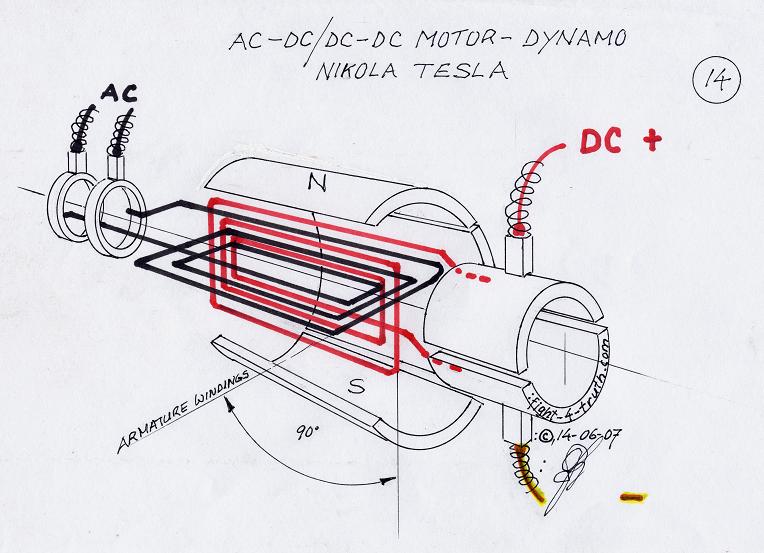
    I'm interested in duplicating some of Tesla's experiments, but have no idea of what exactly he used to provide his smooth high voltage dc into his disruptive discharge circuit back in the 1900s. From his patents I can see it is some kind of dynamo, but that's all i know.

    Can anyone provide me with some clarification as to what he possibly may have used?
    Thanks

  • #2
    In his On Light and Other High Frequency Phenomena Tesla points to what was his source used in his experiments.

    Comment


    • #3
      Teslas Power Supply

      Wow thank you so much!
      This will make a great add to my Tesla collection

      Comment


      • #4
        Tesla's DC Motor Plans

        Here, I managed to get actual plans for it after looking around a little

        Comment


        • #5
          PArAd0X,
          Interesting topic! Have you had any success replicating this yet. What are your intentions. Currently im gathering parts for a dc resonant charging circuit, this will allow me to vary the frequency as im planning on playing with wireless power. Planning on full wave rectifying a few MOT's through a voltage doubler into a smoothing cap and having a variable tank cap and variable rotary spark gap to play with the frequency. Its funny that the typical tesla coil design used now has no frequency adjustment as this was one of the main things tesla was employing in his experements. I read that Tesla also had variable frequency AC generators. If you get one built please post some info on it because i would like to build one too

          Comment


          • #6
            Tesla's discharge mechanism

            You seem to be interested in the same aspects that I am, so I thought I’d share this with you

            I was recently reading this, On Light and Other High Frequency Phenomena, where Tesla describes in great cryptic detail all the functions and parameters of his disruptive discharge primary.

            This is what I deducted from his lecture...

            The primary disruptive discharge system’s main purpose is to deliver the sharpest spike possibly imaginable/perfect square wave and he did this in a very novel manner. For ease of understanding, he compared his system to the image of a large empty water tank.

            This tank would have a medium sized inlet pipe and a huge hole in the base sealed by the force of a tense spring pressing upwards on a plate. When enough water was introduced into the tank the spring would give way under the weight, instantly causing the plate to snap back with it, allowing a gush of water to blast out.

            We can see that the ideal situation involves the fast filling of the tank, but not so fast that spring will have trouble returning to seal the tank again (A sort of natural resonant frequency). This would cause a cycle where the tank repeatedly fills, spring and plate snap back, tank empties, and spring and plate return to seal the tank in a repetitious motion and when this condition is achieved, the system is operating at its ideal requirements.

            The tank represents the main capacitor; the inlet represents the MOT or other power source, the outlet represents the other side of the spark gap and the tension of the spring refers to the various parameters of the arc gap itself i.e. how much power is required to make the spark.

            Tesla only began to make use of rotary spark gaps or other means when he needed to achieve further enhancement. This came as quite a surprise to me because I had initially thought the rotary gap or electromagnet was mainly responsible for the switching, but it turns out that they only complemented the oscillator system.

            With this information I am sure that very powerful enhancements can be made to various Tesla coils and some further understanding can be gained. It is also interesting to note that the frequency adjustment is made by varying capacitor size, spark gap properties and charge input.

            My work

            As far as replicating the illustrated motor, I will probably not because I do not have the money or the resources to build that 50KW beast. I have found a better alternative to begin my research with. I will take 2 huge 50% duty cycle ignition coils and phase conjugate their outputs (when the one is on, the other is off and so on) giving me slightly bumpy DC which will be smoothed by a HV doorknob capacitor. I will feed this into my capacitor/spark gap tank circuit and tune it correctly. Then I will improve efficiency by making use of an additional magnetic spark quencher.

            Since you have practical Tesla coil experience, what are your thoughts on the above information?
            Attached Files

            Comment


            • #7
              I will have to read that article again. Your setup sounds interesting, are you planning to run the ignition coils off of a battery? I have never seen a setup that uses ignition coils that are phase conjugated, interesting idea. I have built a small dc TC from an ignition coil off a battery fed from a pulse width modulator, it was a fun little toy but not very powerful, im not sure how big you can make them with ignition coils but all that i have seen were small. But maybe thats what you are wanting. My last one was running off a neon sign transformer, it had a considerabley more power. And i know my latest plan will have a lot more power than that one, with 2 MOT's running off 240V. You will probably need a charging choke and dequeing diode after your smoothing capacitor to isolate the discharge side from the power side to prevent short circuiting the ignition coils, i would highly recommend reading about dc resonant charging to see what works. Also if you havnt seen it, check out rogerinohio on youtube. A very interesting smart man with lots of experence who put up a wealth of knowledge on youtube. He uses a dc resonant charging circuit.
              YouTube - Overview of my Large tesla Coil
              He also has the best video ive seen on wireless power.
              I will probably be posting all my stuff in the wireless energy thread, good luck, hope to see your work soon

              Comment


              • #8
                Power Source

                I did a little furthur research and realised an ignition coil could not even closely meet my needs, so I decided to go the route you're going and got 2 MOTs today, 2100V 400ma each. Im going to play around with them and collect more over time until I can achieve a phase conjugated network ideally supplying 5000vdc @ +-2 amps/10KW. But for now I need to get my hands on a decent capacitor bank and start work on my first disruptive discharge setup. (Any idea where to source them from?)

                The sole goal of my first disruptive discharge is to achieve some of the effects Tesla reported, like a crown of deadly voltage needles on the primary, and stinging shockwaves penetrating thick, grounded copper plates.

                I’m fairly new to practical work on high voltage systems, MOTs etc. So any advice will go a long way.
                Attached Files

                Comment


                • #9
                  Sounds like some fun things to shoot for, ive been wanting to find the intelligence frequency tesla talks about. You may want to consider a voltage doubler. I have read of people having problems with their spark gap with higher current/ lower voltage like you are describing. Apparently to much current likes to destroy things and not have clean breaks. However doubling the voltage makes it harder to source capacitors. Im probably going to try to make most of mine because HV caps are expensive. MOT's are designed to handle 2000V with no problems, im going to series 2 secondaries which will bump that up to 4000V. Thats twice what they are designed for but lots of guys have done it and they have held up, thats close to your desired 5000V. I dont think i would put more than 4000V through them, i would just let a voltage doubler bump it up from there. Also MOT's are not current regulated, if you put a big load on them, they will just draw current until they fry. So a variac, resistor, or choke may be needed before the transformer. 10KW sounds high for a MOT, i believe they are designed for 1KW, Ive seen guys put 3KW through them safely. You may want to consider a pole transformer, or pig pole transformer as some call them. Please be very careful, thats a big coil for your first one, touching the wrong thing could kill you brother

                  Comment


                  • #10
                    Dont worry im not shooting for 10KW on my first run, i meant to set that as a future target and it will be made up of a whole network of of MOTs, I cant extactly remember where I saw the schematic, but it involves many groups of 2 in series and looks like it means serious business. My first one will consist of 2 transformers, giving an effective output power of 2KW.

                    I never considered homemade capacitors as an option but made with the right materials could probably be a great success. I remember seeing a picture of Tesla's Wardenclyffe lab where he used hundreds of salt water leyden jars in parallel to achieve his capacity.

                    Comment


                    • #11
                      I used homemade saltwater caps on my small ignition coil TC and they worked fine, but it seemed to me that it took a lot of them to get a very small amount of capacitance. But maybe i just designed them poorly. I think im going to try to make some oil filled caps this time, should give me a lot more capacitance per the space it takes up. Im shooting for 5-10uf with at least 10,000V breakdown point for my smoothing cap. Try pricing that out no thanks, ill make my own. Ill have to post that info if its a success, i already have most of the parts, just need to source some transformer or mineral oil.

                      Comment


                      • #12
                        You may have already seen this page guys, but here it is if you havent.

                        Capacitors

                        So far they have been the cheapest source of HV cap for these specific purposes. I have been trying to source some 2-4kv caps around the 3-20uF range for a capacitive discharge system, not unlike grays magnet popping demonstrational unit. So far I have had no luck finding some HV caps, but when I stumbled across this page my hopes were raised. There is oil filled caps there rated 10uF @ 2kv, for $50.00USD.

                        I have emailed them to ask the cost of postage to Australia, but I have not heard back from them.

                        Its a shame, its the cheapest source I can find at the moment, but postage will probably make that moot. Maybe it will help out those who live in the states.

                        Regards
                        "Once you've come to the conclusion that what what you know already is all you need to know, then you have a degree in disinterest." - John Dobson

                        Comment


                        • #13
                          good find ren! Ive just been running the numbers on what it would take to make a similar cap, its going to take lots of aluminum foil, more than i thought Ill keep running some numbers to see about how much its going to cost to make one, but $50 is a great deal. You can get great deals on ebay if you search for high voltage capacitors, but they are in used condition.

                          Comment


                          • #14
                            Great page! I saw it once but lost it .I might consider ordering from them soon.

                            But in the meanwhile did you know that water has a dielectric constant of 80 ! Could it be possible to make a capacitor with distilled water as a dielectric? I have heard of water/methanol combinations used in extremely high powered laser pulse drive systems and particle accelerators.

                            "water" as a dielectric in capacitors
                            Water/Methanol dielectric physics journal

                            Or even ice, apparently it does not conduct at all in its frozen form and has a dielectric constant of 96!
                            Properties of ice
                            Last edited by PArAd0X; 06-13-2009, 06:36 AM. Reason: Bad link

                            Comment


                            • #15
                              Capacitors

                              I've found that a good source for HV capacitors is old microwave ovens. The caps are rated at 2kV but I've been using them at 6kv. I read one site which said testing revealed they don't break down until 10kV. These caps (around 1uF) are on E-bay for $10 to $15 but I find old microwaves in the dumpster all the time. Also, the MW diodes are rated for 12kV to 15kV, but the miliamps are low.

                              Another good source is used, non working defibrillators. There's a used medical equipment supply store nearby, and I got two defibrillators from their dumpster which had 16uF by 7.5kV caps. And I went inside and bought another one for $25 which had a 42uF by 5kV cap - tested above 5.5kV.

                              If you make your own caps, polypropylene is the best HV insulator. It has a K of 2 and a puncture voltage of a few kV per mill. This plastic is used for sheet protectors and crystal clear shipping tape, both at the office supply store. For roll caps, you can trim the edges of the sheet protectors, to separate the sheets, then tape them together end to end. And I like to use heavy duty aluminum foil, but light weight foil will work, as will aluminum flashing from the hardware store. After it's rolled up, put it in a container and add pure water or linseed oil, to increase the dielectric constant.

                              Comment

                              Working...
                              X