Announcement

Collapse
No announcement yet.

Electret experiments

Collapse
X
 
  • Filter
  • Time
  • Show
Clear All
new posts

  • Electret construction structuring

    ? Why not use 3 or 4 little acrilic pillars, they should melt at higher temp.
    Or (Unless it would cause cracking) a cut off an thin acrilic tube of the diamiter you want. would hold the plates up and contain the liquid if sealed with High temp silicone.
    Just a thought
    FrznWtr


    Originally posted by Inquorate View Post
    YouTube - Electret project part 5, baking the cakes

    My wax melted at around 15O degrees celcius. But I didn't account for the cake collapsing when it melted.. Oops. Gotta find something that can handle the heat and hold up the sides..

    Love and light

    Comment


    • Originally posted by Bodkins View Post
      the caps recharging we started it moving and that all it wishes to do (AETHER).
      great stuff coming out of you, mediating on ths stuff really helps me get into a habit of thinking differetly
      I wish i new what to do with your invention?

      electret
      I touch a really old helmet my friend said he can feel the spirit, Me too funny tingle in my hand.
      the same as the electret after it in under weight to get e good contact.
      ether- astral
      a man dieing in battle may leave a astral print,
      Also, making scalar waves with really high voltage dc pulses - take it beyond today's circuitry and really shake the aether, not just slap it on the cheek

      Love and light
      Atoms move for free. It's all about resonance and phase. Make the circuit open and build a generator.

      Comment


      • Originally posted by FrozenWaterLab View Post
        ? Why not use 3 or 4 little acrilic pillars, they should melt at higher temp.
        Or (Unless it would cause cracking) a cut off an thin acrilic tube of the diamiter you want. would hold the plates up and contain the liquid if sealed with High temp silicone.
        Just a thought
        FrznWtr
        Yeah that's the way to go I think. Cut a section of pvc pipe, glue (araldite epoxy can handle the temp) it to a metal disc (cut computer casing etc) for a floor, and at the top, a weighted pie tin hanging from a flexible wire to account for the shrinkage of the wax..

        Another attempt coming soon, electrolyte included

        Love and light
        Atoms move for free. It's all about resonance and phase. Make the circuit open and build a generator.

        Comment


        • Originally posted by Inquorate View Post
          Ps, wax can be re melted and reset; epoxy glue doesn't, and it's expensive
          How about melting transparent plastic and use it instead of wax? maybe with very very thin layer though.
          Last edited by sucahyo; 08-31-2009, 05:09 AM.

          Comment


          • magnetic diode and what else????

            Hello I'm new to the thred
            Watched your Video - Way cool
            Just asking now - did you know that Tesla used mags to Time and Quench
            His spark gaps? Both permanent and electro Magnets. (Prob and silly question huh) Now I'm not sure weather he used them as diodes per-say for direction of flow but he was controlling flow.
            Now begs the question,
            Do you also control what was also passing besides the electrons. Have you considered this at all? Might be a special filter also?????
            Might want to experment to see if it also stops radiant energy.
            Can you build a radiant circuit and test ?/
            FrznWtr


            it seems possible to make a diode using a spark gap and magnets. In the video I have neo and ferrite magnets, but it does work with only ferrite ones.[/QUOTE]

            Comment


            • My New PS

              Lust Bought this for my future experments with Electret makin
              High Voltage, X-ray, HV, Power Supply
              80KV / 15ma, High Voltage Transformer
              80,000 Volt, 15ma high voltage transformer. This transformer is a 60 cycle transformer with a standard laminated steel core. It will run on plain old 50-60 cycle 110 volts, and it does NOT need an inverter like ferrite core high frequency transformers. The transformer is not current limited, so unless your load is current limited like an X-ray tube, then you will need to limit the current input. An example of this concept are the above arc pictures, for these pictures I used a plain desk lamp with a 60watt light bulb to limit the 110v mains current into the transformer primary. It produced an about 1.5 inch, or 3.5cm arc at this power level. My guess is that it is putting out about 50KV with 110V line voltage in.

              The arc in the pictures appears filamentary at this very low 60 watt power level. When you turn up the current, then the arc takes on the more familiar "glowing" arc appearance. The transformer originally had a large 1.5-2kW auto transformer controlling the output kV, in a scientific X-ray machine. At 120V it produces about 60kV, so for the full rated voltage you would need to apply about 140 volts AC. I never ran it over 120Volts, because I did not want to stress my only good reliable source of high voltage, for my X-ray tube. It has not seen much use, only intermittent use. For intermittent use like in short X-ray exposures it can handle up to 1.5KW at <2 Sec. For continuous long run times I would stay under 200 watts.

              I am letting it go because I now have a high frequency HV power supply which is almost completed, but I need the cash to finish it. This transformer is the best one that I have had over the years, I have had others, but this one was simply the best made. This transformer has to be opperated in oil, or it will short out, the best way is to pull at least a moderate vacuum while it is under oil for a few minutes. The other method is to leave it in the oil for a long time, like a week, while periodicaly changing its orientation in the oil to fill all the voids. Slightly heating and cooling the oil helps also to fill the voids. Then ramp up the voltage very slowly with low current to condition it.

              If you need a filament transformer, I have one nice unit available with 50kV above ground isolation, which will run most x-ray tube filaments at up to 100kV (100kV = 50kV- G - 50kV). The winning bidder can have it, and all required HV rectifiers for $75 USD extra, if you want it.

              If you want to drive a voltage multiplier, but you do not want to mess with the electronics of an HF system here is a neat little trick:

              If you feed this transformer with 110 volt 400cycle AC, it will run just fine, and be happy, provided that you stay under 200 watts continuous, and 500watts intermittent. Then if you feed your voltage multiplier with say 25-50kV, at 400 Hz output, then you will get 6 to 7 times more output current, from your existing multiplier, or by the same token, you can now use capacitors with 1/6 - 1/7th of the size needed for a given current at 60Hz line frequency. I mention this because you can now find very cheap motor control inverters on ebay which go up to about 400Hz output. This transformer will work up to about 800-1000Hz so you can even feed it with an audio amplifier as long as you do not go over 1000 Hz, and over 110v input, at this frequency

              The transformer has 2 secondary HV coils, the centertap of these is grounded, with a ground wire lead comming out the side. This also provides a easy way of measuring the output current.while is running. An easy way to limit the current to run this transformer is to use a cheap 175, or 250 watt mercury vapor lamp ballast in series with the primary. With a 175 watt MV lamp ballast in series with the 110-120V mains, it will give you an honest 3ma, at about 50 - 60kV. Wire it so that it does not raise the primary input voltage, so that the MV transformer is in series with the primary only, and then short the secondary with the cap. You could use a high wattage resistor also, but it is much less efficient. It is heavy, about 15+ pounds, but it will fit in a large USPS Flat Rate Box, so you will get your moneys worth from the post office : )
              ---------------------------------
              So what I was wondering???
              Is their anyone in the group that would like to mentor me in its set up and use? Powerful little bugger and I'm not done with my experiments yet Haha
              Last edited by FrozenWaterLab; 03-17-2010, 03:07 AM.

              Comment


              • FrozenWaterLab

                I did end up making a new thread for the diode. And it's already doing weird stuff, it blew up a cfl even though the circuit was off for over an hour.

                http://www.energeticforum.com/renewa...ansistors.html

                Very interested in seeing your Electret experiments posted here

                Love and light
                Atoms move for free. It's all about resonance and phase. Make the circuit open and build a generator.

                Comment


                • Originally posted by FrozenWaterLab View Post
                  Do you also control what was also passing besides the electrons. Have you considered this at all? Might be a special filter also?????
                  Might want to experment to see if it also stops radiant energy.
                  I would be interested in this too. What kind of material do you have in mind?

                  I have been thinking to put some unattached diode to existing one although in reverse direction (I don't have crystal). Just in case it can blow away the slow moving part of the electricity that flow over the wire in reverse with the current inside the wire. And I have been thinking about if adding coil with negating inductance in the radiant circuit will help adding free electron. Don't see the change in low voltage, maybe need to be done in high voltage.


                  Originally posted by Inquorate View Post
                  I did end up making a new thread for the diode. And it's already doing weird stuff, it blew up a cfl even though the circuit was off for over an hour.

                  http://www.energeticforum.com/renewa...ansistors.html

                  Very interested in seeing your Electret experiments posted here

                  Love and light
                  wow , that is a good sign, but also dangerous. Be very carefull with the gasses inside the CFL. The standard procedure is to leave the room for 15 minutes while let the air circulated. The debris should never be touched by hand. Mercury is very bad for health. Odorless, can flow inside the body from skin surface, can make you loose control of your nerve and become crimpled.
                  Last edited by sucahyo; 09-01-2009, 02:00 AM.

                  Comment


                  • will this help?
                    supermagnete.de - FER-01: Ferrofluid 10 ml

                    Comment


                    • StepDown/StepUp (I made up this subject title)

                      below is by Inquorate, I was requested to post this for him.

                      if you had 12v source, and charged 12 caps in series {(+-)(+-)(+-) etc to 1 volt each, whereupon each cap would reach capacity at 1v and flow would stop (so, best to use low loss electrolytic caps, or 2.5 volt 55 farad supercaps)

                      Then to get 6 volts out, wires coming out 2 groups of three caps (+++/---) and (+++/---) connected in series

                      +- +-

                      Should give you 6 volts at higher amps.

                      It would be nice to work out the circuit, especially for my electrets which will be producing high voltage at low amps.

                      I can't cut and paste text on my phone, but if you can, could you put this exchange on my electrets thread?

                      I'm getting geared up for experiments with less fragile Electret mediums, and hope to power a little 12v 100mA fan from the vacuum.

                      Little goal, but maybe achievable.

                      And the capacitor step down circuit will work just fine.

                      by Ben via me

                      Ben, I sent you email to your gmail account...Randy

                      ------------ Added info ------------
                      DC to DC converter - Wikipedia, the free encyclopedia
                      Capacitive
                      Main article: Charge pump

                      Switched capacitor converters rely on alternately connecting capacitors to the input and output in differing topologies. For example, a switched-capacitor reducing converter might charge two capacitors in series and then discharge them in parallel. This would produce an output voltage of half the input voltage, but at twice the current (minus various inefficiencies). Because they operate on discrete quantities of charge, these are also sometimes referred to as charge pump converters. They are typically used in applications requiring relatively small amounts of current, as at higher current loads the increased efficiency and smaller size of switch-mode converters makes them a better choice.[citation needed] They are also used at extremely high voltages, as magnetics would break down at such voltages.

                      ---------------
                      Charge pump circuits

                      ---------------
                      Last edited by Vortex; 09-05-2009, 04:27 PM. Reason: Added Info
                      Remember to be kind to your mind ...
                      Tesla quoting Buddha: "Ignorance is the greatest evil in the world."

                      Comment


                      • How about just creating a sandwich of a hundred or so layers of tinfoil and cling film?

                        Take the lot and throw it into the oven, bake it into a high volume electret with a constant charge applied. If you can maintain the 50v charge for each plate, it becomes a simple problem of surface area.

                        Lets say the epoxy battery earlier had 1 square inch of surface and that generated 50v@26uA .
                        A 10x10" stack of 100 plates with the same charge could be 10,000sq/in surface area, or 50v@380ma.


                        Not sure how you would integrate salts into this setup, I'll leave that to to the rest of you to ponder.

                        Comment


                        • Originally posted by Vortex View Post
                          below is by Inquorate, I was requested to post this for him.

                          if you had 12v source, and charged 12 caps in series {(+-)(+-)(+-) etc to 1 volt each, whereupon each cap would reach capacity at 1v and flow would stop (so, best to use low loss electrolytic caps, or 2.5 volt 55 farad supercaps)

                          Then to get 6 volts out, wires coming out 2 groups of three caps (+++/---) and (+++/---) connected in series

                          +- +-

                          Should give you 6 volts at higher amps.

                          It would be nice to work out the circuit, especially for my electrets which will be producing high voltage at low amps.

                          I can't cut and paste text on my phone, but if you can, could you put this exchange on my electrets thread?

                          I'm getting geared up for experiments with less fragile Electret mediums, and hope to power a little 12v 100mA fan from the vacuum.

                          Little goal, but maybe achievable.

                          And the capacitor step down circuit will work just fine.

                          by Ben via me

                          Ben, I sent you email to your gmail account...Randy

                          ------------ Added info ------------
                          DC to DC converter - Wikipedia, the free encyclopedia
                          Capacitive
                          Main article: Charge pump

                          Switched capacitor converters rely on alternately connecting capacitors to the input and output in differing topologies. For example, a switched-capacitor reducing converter might charge two capacitors in series and then discharge them in parallel. This would produce an output voltage of half the input voltage, but at twice the current (minus various inefficiencies). Because they operate on discrete quantities of charge, these are also sometimes referred to as charge pump converters. They are typically used in applications requiring relatively small amounts of current, as at higher current loads the increased efficiency and smaller size of switch-mode converters makes them a better choice.[citation needed] They are also used at extremely high voltages, as magnetics would break down at such voltages.

                          ---------------
                          Charge pump circuits

                          ---------------
                          I have always thought that insulation would become a problem at high voltage when using a transformer to step-down DC to DC..

                          By what mechanism do '' magnetics break down at high voltage''?

                          Unless they are referring to the usually low current used in high voltage applications; current being the main cause of the magnetic field (if you believe mainstream theory)

                          !?
                          Atoms move for free. It's all about resonance and phase. Make the circuit open and build a generator.

                          Comment


                          • Originally posted by Vortex View Post
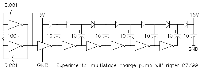
                            ---------------
                            Charge pump circuits

                            ---------------
                            Is that voltage multiplier circuit? since what I recall Peter Lindemann mention that this kind of circuit has very poor efficiency where the diode act as resistor and dissipate more heat than transformer. But since electret making require no current I think this kind of circuit suits well for electret making.

                            Comment


                            • @reiyuki
                              Cling film is very weak for heat. It will shrink and pull itself inward. Good idea though, maybe choose a different type of plastic like turkey bake bags?
                              Hmm.
                              The perforations for air and the wording/labels would present an uneven-ness. Possibly even if they used LAKE color compounds for the words, which are aluminum powder. Don't eat LAKE color. its metal.

                              But good thinking keep using that noggin.

                              @sucahyo
                              Yes it might have losses, but for using to make a free energy battery/cap, its an area of losses I wouldn't mind giving up. I would mind if it was used to run a motor though, or collect ambient voltage.

                              Comment


                              • I was reading what Reiyuki said and then thinking back to a post in the motor threads about high voltage urethane for motor windings.

                                Couldn't we use this here?

                                Take high duty metal foil and coat with grrr, I had the link handy....

                                Anyways it's good up to 20kV I believe.

                                So coat the foil on both sides and let it dry till it's not tacky but still pliable. Roll it up. You could make it any length desired.

                                Probably been down but it hit my brain just now.

                                David

                                Comment

                                Working...
                                X