Announcement

Collapse
No announcement yet.

Tesla's mysterious Phantom Streams

Collapse
X
 
  • Filter
  • Time
  • Show
Clear All
new posts

  • #46
    To Jeff and others,

    What sort of varnish are you using to impregnate your coils? The electric motor rewind factory I work at uses a varnish called Isonel 31 HF by Schenectady for nearly all of our motors and coils. It's one of the better varnishes. I believe that heremetic varnishes are the best but I would need the data sheet to confirm which had the best breakdown voltage. The only problem with these varnishes is that they require a high temperature oven for the varnish to cure properly, usually around 150 C, otherwise the varnish will remain tacky, plus your coil formers will melt if you were using PVC. If you're thinking about going down this path and don't have an oven a rewind shop may be kind enough to let you cure your coils in their oven at no cost. The other option, if you're patient, is to coat each layer in several layers of an air dry varnish, made by Schenectady or Sterling.

    I would also suggest that if you live in a big city find your nearest electric motor rewind supply shop and contact their manager or sales representatives regarding not only the best varnish for high voltage work but materials that you could use in your construction if you don't want to stick with PVC and timber.

    Comment


    • #47
      Pancake coils are usually dipped in transformer oil. There are three main reasons for doing that.

      1. Self-healing properties
      2. It's relatively easy to expel all air bubbles from dielectric
      3. It's a good way to better distribute heat

      As for the special tarnish- I experimented a lot with them regarding helical Tesla coils and found out there is a polyurethane based two-component dielectric that has extremely high breakdown voltage rating and has very low viscosity which makes it relatively easy to expel air bubbles in vacuum chamber. The problem is that if ANY air bubble remains the dielectric will breakdown on that spot. If you ever watched solid dielectric slowly being "eaten" away at the point where air remained you would have immediately consider using liquid dielectric (I am now sorry I didn't use camera on those "expensive" occasions when some air remained in dielectric- it was a very impressive display) . BTW- I had this discussion with Jeff several years back and as it turns out he was correct in using liquid dielectric. Spiral coil windings have to put up with much higher voltages per turn than the helical ones and it's hell if even the smallest pocket of air remains trapped between windings. Transformer oil is harder to work in sense of having to have appropriate container for the coil with but it definitely has its advantages. Also, silk covered wire would be best for using with transformer oil for obvious reasons but it's harder to come by and much more expensive than the enamelled one.

      I think Jeff should explain the winding technique- it's not complicated but it should take some time to properly master it.
      Last edited by lighty; 08-25-2009, 09:23 AM.
      http://www.nequaquamvacuum.com/en/en...n/alt-sci.html
      http://www.neqvac.com

      Comment


      • #48
        Laser / Waterjet / jigsaw

        Originally posted by Jetijs View Post
        Hi Jeff
        Thanks for the answer. Helps a LOT
        I was wondering, what if we took a big copper plate and just laser cut a spiral into it? The laser beam leaves an about 0.3mm wide cut and can handle 1mm between cuts. Then we could slide some mica sheets into the cut slots and submerge it all under oil. This way we could make a large pancake coil without the trouble of winding them. I have access to a laser cutter, but the copper is not cheap so I would like to hear your thoughts about this idea.
        Thank you
        Jetijs


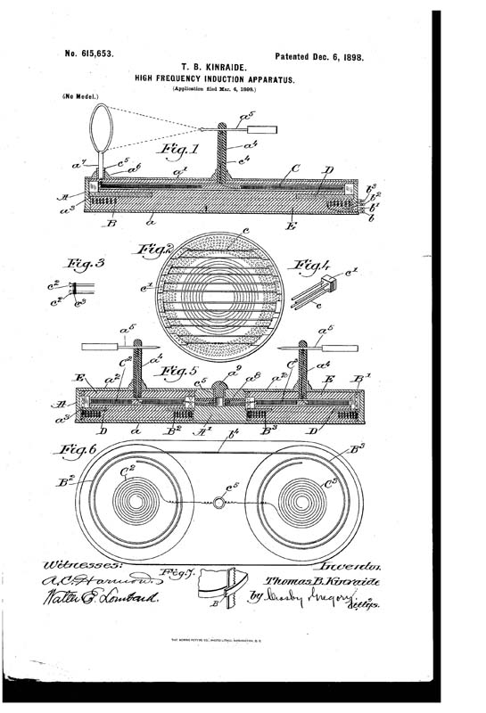
        Kinraide suggested as early as 1898 to use a jig saw to cut to cut the coils! I have personally used a water-jet cutter, which leaves a larger margin (1/32"). I think a laser would be too close, and for copper, sometimes its a problem for lasers with reflectiveness and burning of the lens. (Maybe paint it black or something, which I heard is a solution) But it doesn't mean you couldn't draw in solidworks a flat spiral complete and space the turns how you like. Mylar or acetate will work too as suggested, but...

        The problem with the waterjet or whatever is you end up with a big SLINKY! It is really hard to maneuver around, you have a collapsing flat spiral spring. I did a small sample coil from stainless steel "just to see". It is around 5" OD and a half dozen turns or so 1/32" (jet diameter) between turns. Even in steel it is still very fragile to hold its shape.

        I think its a great idea for the primary winding, but maybe too complicated for the secondary winding. For the primary windings though, I think its excellent. I would be interested in providing you with a drawing for a primary coil in dxf or solidworks 2004 format if you can cut it, and perhaps an extra one for me if it isn't too expensive!

        Comment


        • #49
          etching a coil onto a circuit board

          How about etching a copper pancake coil on to a circuit board?
          Possible?

          Comment


          • #50
            @morpher44

            I did that a few years back and it's certainly possible to get very thin windings if you use proper photo-etching film. However the coil then must be submerged in transformer oil and you can forget about additional solid dielectric between windings (which could be a problem if you're aspiring to higher voltages). I used such coil in a slightly different configuration but it produced HV without any problem whatsoever although I had to be careful about the breakthrough voltage of oil so it was a limiting factor. Also because of the relatively thinner surface between two windings inter-winding capacitance was reduced and I had to compensate for it which to a certain extent took some of the advantages of pancake coils. However it's very easy and cheap to produce if you know what you're doing.

            BTW- Jeff is correct it's extremely easy to draw Archimedean spiral in Solidworks (especially in newer versions) and then you can export it as DXF or even PDF and make film out of it.
            Last edited by lighty; 08-25-2009, 11:36 PM.
            http://www.nequaquamvacuum.com/en/en...n/alt-sci.html
            http://www.neqvac.com

            Comment


            • #51
              Yes Jeff, the slinky thing is what I also suspected could be a problem and you verified this. There are many copper grades, some are softer and easier to bend and some are very hard. For this idea we should try the harder grade of course. I think that thicker plate could also be of some advantage. I will try some test cuts and then we will see but this will not be fast. If all goes well, I will make some primaries also for you
              Thanks,
              Jetijs
              It's better to wear off by working than to rust by doing nothing.

              Comment


              • #52
                When using water cutter you could use much harder grill with wider openings on which to put your copper plate that is to be cut. Or you could use thicker steel plate on which to put copper plate to be cut (I think such plate would have to have grooves to allow for water and silica to be drained. If you set your water jet correctly it would cut through copper but not through grill or thick plate (at least not completely). However if you move your nozzle too far away from copper or reduc water jet pressure it could provide you with too wide cuts.

                IIRC Jeff is working with water cutting equipment on daily basis so he could prove me wrong.
                http://www.nequaquamvacuum.com/en/en...n/alt-sci.html
                http://www.neqvac.com

                Comment


                • #53
                  Hello everyone
                  Today I visited the water jet guy and we tried to cut a pancake coil out of 1mm thick stainless steel plate just to test how it would work. We had time only for one try. The water jet nozzle is about 1.3mm in diameter, that leaves just as wide cut behind. We drew the spiral so that it would make a coil with 1mm wide wire and there would be 1.3mm space between windings. Well, the result was a deformed slinky, because the water jet just has too much power blasting on that plate and there is water everywhere with waves coming up from underneath the base grid. This waving and bubbling is constantly moving the already cut out parts. Anyway, water jet wont work for this, maybe if the turn width and the plate thickness would be greater it would work better, but not for coils this small and thin. But as for the primary coils, I see no problems there I don't have a camera at hands now so I can't show you the result, but it is nothing beautiful Will now try the same with a laser cutter
                  Thanks,
                  Jetijs
                  It's better to wear off by working than to rust by doing nothing.

                  Comment


                  • #54
                    You can put additional heavy upper plate to form a kind of "sandwich". The problem is that water jet have a tendency to diverge as it goes through the material so you would get much wider cutting width.

                    Anyway, for the moment laser seems like a better idea but I think when everything is said and done you will end up winding the coil good old fashioned way. Although I have a different idea which might be a bit more complicated but could provide you with a possibility of making PCB secondaries with extremely high breakthrough voltage. I have to check out tables of some isolation materials I worked with just recently. Stay tuned.
                    http://www.nequaquamvacuum.com/en/en...n/alt-sci.html
                    http://www.neqvac.com

                    Comment


                    • #55
                      Lighty, you are probably right, eventually I will have to wind the coils the old fashioned way But I still will try to cut the coil with a laser cutter.

                      Can't wait for your PCB idea

                      Another way to wind the coils easily would be to get some flat ribbon wire and wind that between two spacer plates along with some kind of insulation material that could later be soaked with transformer oil. Unfortunately I don't know where to get such a wire. Interesting, what would the electrical characteristic of such a coil be? I guess the capacitance would increase.

                      Thanks,
                      Jetijs
                      It's better to wear off by working than to rust by doing nothing.

                      Comment


                      • #56
                        Yup capacitance would rise significantly. However those coils Jeff makes are wound with round wire. I remember the technique of winding as he described it to me a few years back but I really ought to leave explanation to him.

                        As for the PCB idea- it would not be made with ordinary PCB material. I'm still looking through data. Stay tuned!
                        http://www.nequaquamvacuum.com/en/en...n/alt-sci.html
                        http://www.neqvac.com

                        Comment


                        • #57
                          Are there PCB plates that have a thicker copper layer on them than usual? Another way could be engraving the spiral on them with a cnc engraver. This way the cuts could be deeper than the layer of copper, but not the whole way through. The deepening between the turns would be advantageous because when filled with oil, there would be much greater HV insulation between turns than on just ordinarily etched PCB's under oil.

                          It's better to wear off by working than to rust by doing nothing.

                          Comment


                          • #58
                            coils on pcb in series

                            Originally posted by lighty View Post
                            BTW- Jeff is correct it's extremely easy to draw Archimedean spiral in Solidworks (especially in newer versions) and then you can export it as DXF or even PDF and make film out of it.
                            Rather than one large coil on a PCB, would several smaller
                            pancake coils, arranged in a matrix and connect in series -- yield
                            a large inductance?
                            Also, bifilar pancake addresses the capacitance issue.

                            If the outer diameter is say X meters, then it might make sense
                            for each coil in the array to be spaced in such a way that their
                            rotating magnetic fields can be mutually inductive SPIN-wise --
                            such as 3 circles in a triangle or a row of 3, then 2, then 1 for
                            a total of 6, etc.

                            Comment


                            • #59
                              Originally posted by Jetijs View Post
                              Are there PCB plates that have a thicker copper layer on them than usual? Another way could be engraving the spiral on them with a cnc engraver. This way the cuts could be deeper than the layer of copper, but not the whole way through. The deepening between the turns would be advantageous because when filled with oil, there would be much greater HV insulation between turns than on just ordinarily etched PCB's under oil.
                              Haha, you're reading my mind. However I was considering gluing copper sheet to insulation material. In that way one could get thicker layer of copper then in normal PCB and use photo-etching to make grooves. However if the layer is too thick then acid would eat through groove material on the sides. That could be addressed by precisely timing and controlling etching process and by awoiding using too thick copper. Then in the groves I would present paper of better yet cellulose material which would get saturated with oil after the whole rig is submerged in oil. One could also introduce mylar and then dip everything in the oil but electric field gradient would then be stretched in such way to put additional strain either on mylar or on oil depending on the dieletric parameters of both materials. I guess paper could do fine.

                              There are CNC machines capable of producing PCBs for prototyping. However I never checked their tolerances and they are not so common. If you're sure you can use CNC machine to make very narrow grooves then the solution with gluing copper sheet of some thickness (between, let's say 0.2-1.0mm) on dielectric material like some epoxy resin plate or bakelite could prove as relatively easy way of producing secondary. Of course I would prefer for tool to cut a bit into the dielectric so that paper can get a bit under the lower level of copper sheet.

                              Also, when gluing copper sheet it would have to be done in a rather precise way so it would have to be done by using appropriate press to stick copper sheet to dielectric material until the glue fully hardens.

                              I think we're on to something here. In the past I used two component polyurethane compound which has extremely high viscosity when not activated so vacuuming would suck all of air bubbles out of it and it would fill the grooves completely. When fully hardened it's breakthrough voltage is ~70kV/mm (which is extremely high). However it's a value for frequencies from DC-100Hz I simply cannot find data for higher frequencies. The price of 1l of that polyurethane compound is ~60EUR (at least here in Croatia but I think the price is pretty much the same in EU as well).

                              What's your take on CNC precision?

                              I think all of the above described is achievable in a relatively easy and cheap way.
                              http://www.nequaquamvacuum.com/en/en...n/alt-sci.html
                              http://www.neqvac.com

                              Comment


                              • #60
                                Great idea
                                With my homebuilt cnc machine I should be able to engrave a coil with a 1mm turn width and 1mm turn spacing easily. I have not tried anything smaller, but I think that 0.5mm width and spacing is also achievable with good precision. The machine uses 200 step per turn step motors and operates at 1/4 step mode, that gives 800 steps per revolution. The leadscrew pitch is 4mm, so the theoretical precision is 0.005. Practically it is less precise, but the offset should not be greater than 0.1mm so I guess the precision is good enough for this purpose. Will get some standard blank PCB boards tomorrow and do some tests
                                Thanks,
                                Jetijs
                                It's better to wear off by working than to rust by doing nothing.

                                Comment

                                Working...
                                X