Announcement

Collapse
No announcement yet.

Tesla's mysterious Phantom Streams

Collapse
X
 
  • Filter
  • Time
  • Show
Clear All
new posts

  • Self-Induction Coils...

    Busy as anything now. Some completed spark gap photos of new design in a day or two to be posted here and on the site. Also, some interesting experiments using early radio tuning coils (Deforest, etc.) of unusual designs for new applications in Tesla Coil power supplies. I tested some theories briefly in the lab that really surprised me with the results. Will be looking forward for everyone's input and ideas later on this week...espescially those who want some adventurous coil designs. Some of the early winding techniques for radio inductances were one step more confusing than a rubix cube!

    Jeff
    Comment


    • Originally posted by jeff_behary View Post
      Busy as anything now. Some completed spark gap photos of new design in a day or two to be posted here and on the site. Also, some interesting experiments using early radio tuning coils (Deforest, etc.) of unusual designs for new applications in Tesla Coil power supplies. I tested some theories briefly in the lab that really surprised me with the results. Will be looking forward for everyone's input and ideas later on this week...espescially those who want some adventurous coil designs. Some of the early winding techniques for radio inductances were one step more confusing than a rubix cube!

      Jeff
      Jeff,

      When you posted images of positive streamers pulling electrons from metallic ball I immediately thought about connecting incandescent bulb between such metallic ball and Earth ground.Do you think it will blink on each discharge ?

      Comment


      • Ball terminal

        Originally posted by boguslaw View Post
        Jeff,

        When you posted images of positive streamers pulling electrons from metallic ball I immediately thought about connecting incandescent bulb between such metallic ball and Earth ground.Do you think it will blink on each discharge ?
        The phantoms disappear when the coil has its energy used (connected to a tube or bulb), or drawing normal oscillatory portions of the sparks near the ball. If left free, the phantoms reach out and can be used for other things (like charging an external ball or cap). A number of items can be charged at once with them positioned around the coil, but the moment the coil is "drained" they normally disappear in the same way that brush discharges do when a typical operating coil is loaded...

        Jeff

        Comment


        • Originally posted by jeff_behary View Post
          The phantoms disappear when the coil has its energy used (connected to a tube or bulb), or drawing normal oscillatory portions of the sparks near the ball. If left free, the phantoms reach out and can be used for other things (like charging an external ball or cap). A number of items can be charged at once with them positioned around the coil, but the moment the coil is "drained" they normally disappear in the same way that brush discharges do when a typical operating coil is loaded...

          Jeff
          than put big plate(capacitor) near phantom streamer and connect bulb to earth

          I ll try some experiments this way...

          Comment


          • Video

            Originally posted by grizli View Post
            than put big plate(capacitor) near phantom streamer and connect bulb to earth

            I ll try some experiments this way...
            The Turn Of The Century Electrotherapy Museum Tesla Library

            I did something similar with a collector and cap, but earthed to the coil instead of ground. I didn't light any incadescent bulbs though.

            Video:
            YouTube - Static Electric Machine made from Tesla Coil (Pancake Coil, Phantom Streamers)

            It seems to be a nice static machine for high humidity...

            Comment


            • Originally posted by jeff_behary View Post
              The Turn Of The Century Electrotherapy Museum Tesla Library

              I did something similar with a collector and cap, but earthed to the coil instead of ground. I didn't light any incadescent bulbs though.

              Video:
              YouTube - Static Electric Machine made from Tesla Coil (Pancake Coil, Phantom Streamers)

              It seems to be a nice static machine for high humidity...
              I know all this video , I didnt mean t hat..

              let me be more detailed, ps i just did what I will describe:

              Take 5mm acrylic plate (or thicker) if you dotn have thicker make TC output to minimum, small power less than 200W near 1/4 wavelength for virelength, and let it produce phatoms in darkness...

              on one side of acrylic attach one sheet of metal and on another side also, but at least 5-10 CM far from edges to prevent sparks go over edges...

              and make metal sheet have round edges(you can use aluminum foil)

              conect one side of capacitor to TC directly , and if you put object near other side of capacitor there will be PHantom sparks, acrylic will prevent current sparks...

              if you put object closer there will be classic current sparks between object and capacitor metal plate...

              Some people think its due ambient energy..
              I havent tested but also is claimed that you can conect some load from other capacitor side and ground, and TC will run freely...

              also you dont have to ground other TC side to prevent AC goes through earth to get closed loop

              you can use battery powered TC to that experiment(not conected to earth) there will be always strong spark between other capacitor side and earth (or pahtom if you move object more away)

              ALSO object affected by phantoms this way has DC charge after DC is unplugged

              Comment


              • Velocity Coil

                Hello Jeff. I hope you remember me, I finally finished the velocity coil core that we had discussed a while back. Due to an on the job injury and workers comp I have been unable to test it yet due to financial crap. Would you like to borrow this to see what you can get it to do?
                Attached Files

                Comment


                • Your Coil

                  Originally posted by martin View Post
                  Hello Jeff. I hope you remember me, I finally finished the velocity coil core that we had discussed a while back. Due to an on the job injury and workers comp I have been unable to test it yet due to financial crap. Would you like to borrow this to see what you can get it to do?
                  Martin,
                  Yes, I remember you called a while back. I'd be happy to test it for you if you pay shipping costs. I imagine it can fit safely in a small priority mail box. Just give me an idea of how many layers/turns, so I can guestimate what sort of circuit to use.

                  Jeff

                  Comment


                  • Originally posted by ren View Post
                    Hi guys,

                    Love your work. I dont have any glow from it yet but I thought Id share a picture of the tower my friend is working on. You can see the conical coil in the center and the primary at its base.

                    All the tower is made from wood. The sphere is littered with brass studs.

                    Hopefully with some help we can get a purple glow happening.
                    Wow man! That is pretty incredible. I hope you've been having success testing with this. I'm actually in the process of setting up plans to make custom capacitors as per Tesla's patent 567,818; which is supposed to respond very well to high frequency current as stated by him on line 35 of the patent.

                    Has any one else already done this, or are can they provide feed back regarding it?

                    I also plan on trying to make his coil for electro-magnets as per patent 512,340.

                    Jeff, I have looked through at your work posted here (need to reread everything a few more times) and over at the electrotherapy site. You get my respect for being a man of action and not of words. I'm trying very hard to move along as quickly as I safely can in doing the same. I recently replicated one of Tesla's high frequency patents #568,176, for high frequency current. It's quite amazing to see the difference in performance when more ideal transformers are implemented. I'm actually going through and trying to optimize each section of the circuit (I think the specially wound magneto-coils could be an ideal secondary for this circuit.).

                    One more question for folks working with high frequency current: Have any of you experience in building high frequency circuits based on Tesla's early 462,418 circuit? Where he uses a capacitor, air gap, and transformers instead of a mechanical, motorized spark gap? I've been using FETs and I have a strong feeling that they are not ideal. I'd like to hit the million Hz mark but haven't had enough time to research optimal (cheap) options.

                    I do know that Tesla says in patent 454,622: "...but I would make it clear that as to the inferior lower limits of both, the lowest frequency and potential that I contemplate using are far above what have heretofore been regarded as practicable. As an instance of what I regard as the lowest practicable limits I would state that I have obtained fairly good results by a frequency as low as fifteen thousand to twenty thousand per second and a potential of about twenty thousand volts. Both frequency and potential may be enormously increased above these figures..."

                    If any one else has had success with this and have a thread posted on it, please share. I am searching through threads but I don't want to miss any thing.

                    Regards.

                    Comment


                    • I'm curious if anyone can replicate the phantom streamers readily at this point.

                      Comment


                      • Absolutely great work. I can offer a bit of speculation as I have done quite a bit of work in this area, but have to say your craftsmanship is bar none top notch. Stick with me and hopefully you will see where I am going.

                        The pancake coil is interesting to me because of its inherent shape. A while back I began to think of a new way to describe phenomenon by "re-inventing" math. We seem to be stuck in a linear world from my point of view. We use linear mathematics to describe rotational systems. Moving from the line to area and volume (with respect to circular and spherical geometry) requires Pi, and other transforms. Every system of math starts with 1 as a linear progression and modifies from this point.

                        Radius = r
                        Area of circle = pi * r^2
                        Volume of sphere = (4/3) * pi * r^3
                        (First, Second and third "dimension")

                        We may however transform many things and set our beginning point to "1" (not zero). For example (simple) we may decide that we will not begin with a linear progression, and start our new math by setting area equal to volume....thereby deriving the first dimension rather than just naming it off the bat so to speak. So lets set pi * r^2 equal to (4/3) * pi * r^3. r now equals 1.7671. At this r, both are equal. WHO CARES????

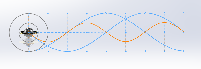
                        Well, in the world of point sources and dipoles the "spreading" of fields is 1/r^2 and 1/r^3 respectively. Electric point source + Magnetic dipole at 90 degrees (poynting vector) = observable reality (power or interaction)) So if we wanted to find the "shell of strongest interaction" we would find a dipole geometry, and point source geometry which complement each other to create a chosen "valence" of greatest interaction. Continuing this train of logic, we can say the dipole should be a ring (no need to go into proof but it creates the best possible dipole of 1/r^3 at a distance) and the point source (electrostatic) a sphere. One double the radius of the other.

                        A few photos.


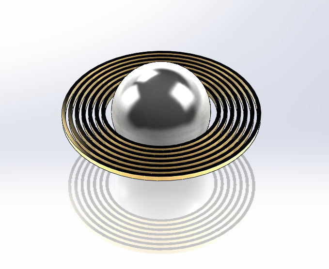
                        Here you see the center point source, the disk dipole, and the ring at which they interact most strongly. This is assuming resonance within the structure at the fundamental harmonic. The two blue lines are the 90 degree phase differential meeting at the 45 degree mark on the outer grey circle. The orange line is the magnitude of interaction between the two. Here are a few more graphical representations.


                        EmittergeometricRelations_zps1d5ce248.png Photo by tortuga0303 | Photobucket

                        http://i210.photobucket.com/albums/b...ps7b421751.png
                        Electric

                        http://i210.photobucket.com/albums/b...ps444674d8.png
                        Magnetic

                        http://i210.photobucket.com/albums/b...psaaacab0f.png
                        Interaction

                        http://i210.photobucket.com/albums/b...ps5498bda7.png
                        All together in 3d plus interaction

                        Now consider that the true nature of such systems is a harmonic spectrum, not single frequency. Enter the FFT solution to the wave equation.....

                        Traveling Wave Equals Sum of Stationary Modes - YouTube

                        All together, the only shape which can accomplish everything mentioned is a geometry very very similar to the pancake coil. Something to chew on.

                        Comment


                        • I'm confused at what you mean...

                          What does this have to do with Tesla's Phantom Streamers?

                          Comment


                          • Originally posted by Tenaus View Post
                            I'm confused at what you mean...

                            What does this have to do with Tesla's Phantom Streamers?
                            Well.... Each turn in a spiral has a different ratio of inductance to capacitance to the turns next to it. This creates a situation optimal for a harmonic distribution in resonance (at all modes slower than the initiating impulse not counting the effect of superposition of waves). A more complete spectrum of related frequencies are possible in this configuration. Also the magnetic component can be placed toward the periphery and due to its disk like configuration the inverse cube law of dipole radiation is most closely approximated while the central capacitance being of inverse square fall off allows for a more spherical interaction (poynting vector) at a distance. In other words this more closely mimics nature. It is a "fractalized wave guide" which creates interesting patterns in nearfield.

                            Why do you think there are fractalized streamers? Multiple modes of resonance. However the streamers inherently change the capacitance constantly which is no good. Do without.

                            Comment


                            • Originally posted by Armagdn03 View Post
                              Why do you think there are fractalized streamers? Multiple modes of resonance. However the streamers inherently change the capacitance constantly which is no good. Do without.
                              Are you sure? Jeff has consistently reported that no re-tuning of the coils are required after, or during, interaction with the streams. The resonant frequency doesn't change, and hence, capacitance and inductance to not change due to these streams.

                              In fact, they almost seem like they do not exist at all, since there can be nothing felt from them, nor can we digitally capture these streams.

                              It makes me doubt the very existence of phantom streams.

                              Well.... Each turn in a spiral has a different ratio of inductance to capacitance to the turns next to it. This creates a situation optimal for a harmonic distribution in resonance (at all modes slower than the initiating impulse not counting the effect of superposition of waves). A more complete spectrum of related frequencies are possible in this configuration. Also the magnetic component can be placed toward the periphery and due to its disk like configuration the inverse cube law of dipole radiation is most closely approximated while the central capacitance being of inverse square fall off allows for a more spherical interaction (poynting vector) at a distance. In other words this more closely mimics nature. It is a "fractalized wave guide" which creates interesting patterns in nearfield.
                              To clarify, you mean to say that whatever situation there is with inductance and capacitance... when in resonance, the coils at the moment phantom streams issue from the top load are oscillating not only at the frequency of the driving circuit, but also of harmonic undertones?

                              Perhaps, but I think it is rather useless to try to attempt to explain a phenomenon which we still do not completely understand.

                              First, the fact that these streams are almost invisible to empirical methods of measurement is interesting. It makes me doubt the very existence of the streams themselves, since there technically is no proof for their existence. My goal is to reproduce them, and subsequently investigate the properties of these streamers.

                              Next, as I said, I think we should first investigate the properties of these streams until we understand their behavior. We then can theorize on the cause.

                              The very first thing we should do in this regard, is to devise a method of reproducing the phantom streams reliably, such that others in the scientific community may study them, and obviously for our own study as well. There has been no reliable method of producing these phantom streamers. They are very mystical and unscientific as far as I am concerned until we secure proper methods of their reproduction.

                              We cannot move forwards until this happens. I am interested in what you believe can reproduce this phenomenon.

                              Tesla describes in his 1892 lecture "Experiments with Alternating Current of High Potential and High Frequency" the method which produces phantom streams. He used this coil to show the phantom streams:


                              Alternate spark-gap:


                              This is a very common set up, so it is curious that we don't see phantom streams more often. Additionally, I would say that the spark gap in fig. 6 and fig. 7 would be the most optimal one for this, as Jeff once described how the effect is mostly seen with 2 gaps.

                              He continues to explain the phenomenon:

                              When an ordinary low frequency discharge is passed through moderately rarefied air, the air assumes a purplish hue. If by some means or other we increase the intensity of the molecular, or atomic, vibration, the gas changes to a white color. A similar change occurs at ordinary pressures with electric impulses of very high frequency. If the molecules of the air around a wire are moderately agitated, the brush formed is reddish or violet; if the vibration is rendered sufficiently intense, the streams become white. We may accomplish this in various ways. In the experiment before shown with the two wires across the room, I have endeavored to secure the result by pushing to a high value both the frequency and potential; in the experiment with the thin wires glued on the rubber plate I have concentrated the action upon a very small surface—in other words, I have worked with a great electric density.


                              A most curious form of discharge is observed with such a coil when the frequency and potential are pushed to the extreme limit. To perform the experiment, every part of the coil should be heavily insulated, and only two small spheres—or, better still, two sharp-edged metal discs (d d, Fig. 11) of no more than a few centimetres in diameter—should be exposed to the air. The coil here used immersed in oil, and the ends of the secondary reaching out of the oil are covered with an airtight cover of hard rubber of great thickness. All cracks, if there are any, should be carefully stopped up, so that the brush discharge cannot form anywhere except on the small spheres or plates which are exposed to the air. In this case, since there are no large plates or other bodies of capacity attached to the terminals, the coil is capable of an extremely rapid vibration. The potential may be raised by increasing, as far as the experimenter judges proper, the rate of change of the primary current. With a coil not widely differing from the present, it is best to connect the two primaries in multiple arc; but if the secondary should have a much greater number of turns the primaries should preferably be used in series, as otherwise the vibration might be too fast for the secondary. It occurs under these conditions that misty white streams break forth from the edges of the discs and spread out phantom-like into space. With this coil, when fairly well produced, they are about 25 to 30 centimetres long. When the hand is held against them no sensation is produced, and a spark, causing a shock, jumps from the terminal only upon the hand being brought much nearer. If the oscillation of the primary current is rendered intermittent by some means or other, there is a corresponding throbbing of the streams, and now the hand or other conducting object may be brought in still greater proximity to the terminal without a spark being caused to jump.

                              Among the many beautiful phenomena which may be produced with such a coil I have here selected only those which appear to possess some features of novelty, and lead us to some conclusions of interest. One will not find it at all difficult to produce in the laboratory, by means of it, many other phenomena which appeal to the eye even more than these here shown, but present no particular feature of novelty.
                              So, thoughts?

                              Comment


                              • Originally posted by Tenaus View Post
                                Are you sure? Jeff has consistently reported that no re-tuning of the coils are required after, or during, interaction with the streams. The resonant frequency doesn't change, and hence, capacitance and inductance to not change due to these streams.

                                In fact, they almost seem like they do not exist at all, since there can be nothing felt from them, nor can we digitally capture these streams.

                                It makes me doubt the very existence of phantom streams.


                                To clarify, you mean to say that whatever situation there is with inductance and capacitance... when in resonance, the coils at the moment phantom streams issue from the top load are oscillating not only at the frequency of the driving circuit, but also of harmonic undertones?

                                Perhaps, but I think it is rather useless to try to attempt to explain a phenomenon which we still do not completely understand.

                                First, the fact that these streams are almost invisible to empirical methods of measurement is interesting. It makes me doubt the very existence of the streams themselves, since there technically is no proof for their existence. My goal is to reproduce them, and subsequently investigate the properties of these streamers.

                                Next, as I said, I think we should first investigate the properties of these streams until we understand their behavior. We then can theorize on the cause.

                                The very first thing we should do in this regard, is to devise a method of reproducing the phantom streams reliably, such that others in the scientific community may study them, and obviously for our own study as well. There has been no reliable method of producing these phantom streamers. They are very mystical and unscientific as far as I am concerned until we secure proper methods of their reproduction.

                                We cannot move forwards until this happens. I am interested in what you believe can reproduce this phenomenon.

                                Tesla describes in his 1892 lecture "Experiments with Alternating Current of High Potential and High Frequency" the method which produces phantom streams. He used this coil to show the phantom streams:


                                Alternate spark-gap:


                                This is a very common set up, so it is curious that we don't see phantom streams more often. Additionally, I would say that the spark gap in fig. 6 and fig. 7 would be the most optimal one for this, as Jeff once described how the effect is mostly seen with 2 gaps.

                                He continues to explain the phenomenon:


                                So, thoughts?
                                I have seen these before in my own experiments, and am quite diligent in perusing my understanding of the principles. The plasma created acts as a surface area extension to the top load. Since the coils are not being run at a singular frequency, rather are being excited by impulse, the harmonic spectrum will adjust itself in many ways. However when trying to really understand what is happening, it becomes more difficult when you have an initial point say 1,2,4,8 of harmonics which then shift to 1.1,2.2,4.4,8.8. This is a second order oscillation between harmonic spectra in the frequency rather than time domain.

                                Yes I am absolutely saying there are more than one frequency involved. Lets take a look at the capacitance only and observe an interesting slice of this "mystery". The inter turn capacitance from one coil winding to the next will change as the surface area of one is in ratio with the next. Loking at only two turns:

                                Say we excite the outermost winding with a dielectric impulse. The inner winding will create a condenser, with the outer. Because there is a larger surface area on the outer than inner, and knowing that charge conservation holds we must say that the charge density differs. You essentially have a capacitive transformer (Gauss Law). a good example shown below using spheres.

                                Spherical Capacitor

                                Therefore extended, you have a changing potential gradient from periphery toward center. If the impedance of the impulse is greater for the inductance of the structure than the capacitance, then this phenomenon will become more pronounced. Same goes for the inductance gradient.

                                As one moves from out to in the ratios of capacitance and inductance change in a complex manor, creating conditions which may accommodate complex multi-frequency excitation. Smaller rings are more suited to higher frequency and potential owing to the values of C and I. Larger more suited to lower for the same reason.

                                A cylindrical wave-guide can also accommodate many harmonics, however the capacitance and inductance from winding to winding stays relatively similar, meaning your harmonic spectrum is held closer to whole ratios, rather than fractal ratios. The conical, or the pancake style may hold many more related harmonics which are not seen in a traditional Tesla secondary.

                                Apply this to the superposition of waves to find the dominant frequencies within the given spectrum. Dollard created an interesting Bipolar transformer which accomplished very similar results using two separate em sources rather than a structure which contained the necessary ingredients within one structure.

                                Comment

                                Working...
                                X