Announcement
Collapse
No announcement yet.
Hendershot Replications
Collapse
X
-
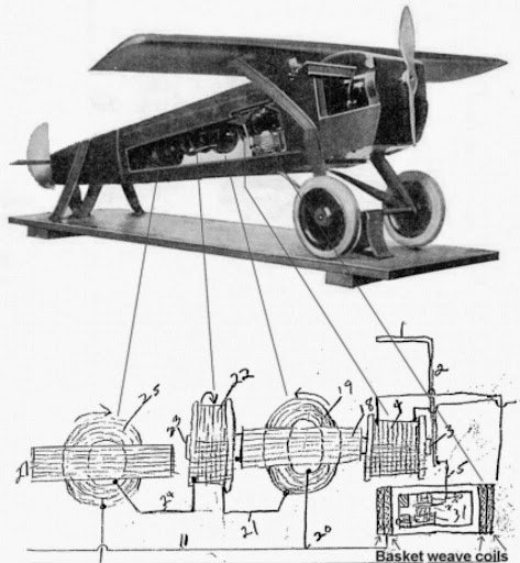
Ok in the photo above is the Basket Coil lying down in the front is it just a Diagram for the Basket Coil standing up
and I bet that front coil had magnets in it thats what will be in the Basket lying down with the window in it they will be magnets inside that windowLast edited by Gazzasore; 02-05-2013, 03:21 PM.
Comment
-
Got it
https://www.youtube.com/watch?v=xPAX...ture=endscreen
https://www.youtube.com/watch?v=EyBISrhz5Cs
https://www.youtube.com/watch?featur...&v=NJ7saXwMYUU
https://www.youtube.com/watch?v=KaOf...endscreen&NR=1
and the other Basket coils must had induced and produced enough power for the motor to runLast edited by Gazzasore; 02-05-2013, 03:37 PM.
Comment
-
Originally posted by Gazzasore View PostGot it
https://www.youtube.com/watch?v=xPAX...ture=endscreen
https://www.youtube.com/watch?v=EyBISrhz5Cs
https://www.youtube.com/watch?featur...&v=NJ7saXwMYUU
https://www.youtube.com/watch?v=KaOf...endscreen&NR=1
and the other Basket coils must had induced and produced enough power for the motor to run
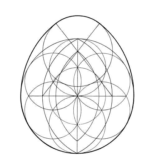
the shape of the coil looks almost egg like https://www.youtube.com/watch?featur...&v=NJ7saXwMYUU

also considered a favorable aerodynamic shape “Signs and symbols rule the world, not words nor laws.” -Confucius.
Comment
-
seems very large
Yes I would suggest that is a horseshoe magnet.
It does look "special" in that you probably couldn't purchase
that necessarily off-the-shelf. Hendershot may have had
access to help from Army engineers and "special" custom
made improvements over the many years he worked on this.
Notice how that magnet has a circular shape, very similar
to the cylinders. They are likely the same diameter on purpose
and in that orientation to create 3 spinning oscillations,
spinning in the same direction -- cw, then ccw...
The tranformers placed in the cylinders, I suspect, was just
to save space and not necessarily crucial to success.
However, on the other hand, I have two of these 5to1
transformers and I'm struck by how nicely they do work
as "pickup coils". You get a NICE pick up since the laminations
in the coil respond very effectively to nearby magnets even
to the point of bumping the table and noticing a SPIKE.
So it may not HURT to put them nearby any oscillating
magnetic field... as long as the PHASE allows for
constructive interference into the circuit.
Hendershot may have been able to MAP OUT on his board
where are the fields are -- being a master with induction compass,
compasses, coils, mutual induction. After plotting where all the
fields are, he could then probably MOVE his coils around on the
board to maximize constructive interference.
Since winding coils is an imprecise science, and components
have certain tolerances such a 5% less than you think or 5% more...
the understanding of what the waveforms might look like --
such as using an oscilloscope, may have been a necessary
part of the "tuning" step. It is impressive that he could somehow
figure it out in his head w/o seeing the waveforms. This may have
come with experience, having done it so many times over and over
again using his "rote" work-ethic. Us youngin's are so impatient. We
just want to switch it on and see it work w/o knowing why.
Comment
-
Morpher wrote
""They are likely the same diameter on purpose
and in that orientation to create 3 spinning oscillations,
spinning in the same direction -- cw, then ccw...""
I wonder if this has anything to do with Tesla always working in 3's
Here in Thailand now some power lines where there are 3 wires have a spacer that makes a Triangle shape I believe there is less power loss with this configuration
Comment
-
5 to 1
If 220VAC is the input, then 44VAC needs to be the output to beOriginally posted by Gazzasore View PostMorpher these 5 to1 Transformers
What would be written on them Here in Thailand its 220v
I mean I dont understand what to buy
5to1. I purchased transfomers that have 120VAC input, 24VAC output.
Center taps might be present and they would just not be hooked up.
I might also add that in the USA, the standard is 60Hz so these transformers
might be ideal around that frequency. This is not strictly the case, however,
since I think these transformers can be pretty wasteful and might be
off-tune.
Comment
-
Originally posted by morpher44 View PostIf 220VAC is the input, then 44VAC needs to be the output to be
5to1. I purchased transfomers that have 120VAC input, 24VAC output.
Center taps might be present and they would just not be hooked up.
I might also add that in the USA, the standard is 60Hz so these transformers
might be ideal around that frequency. This is not strictly the case, however,
since I think these transformers can be pretty wasteful and might be
off-tune.
Ok so its a step down Transformer Well there you go I always thought it would had been up
Ok so its a 220 VAC down to 44 VAC thanks
Hey odd things happening here on the site
I get your new post by email but they are not showing on the site
Comment


Comment