Announcement

Collapse
No announcement yet.

Donald Smith Devices too good to be true

Collapse
X
 
  • Filter
  • Time
  • Show
Clear All
new posts

  • soundiceuk
    replied
    Originally posted by Wistiti View Post
    Hahaha!
    Thanks Paul for the reply but I'm not mean long in time but in length of wire... for ordering some hv wire! my English is not always good as i want!
    But i may take the time to take a coffee wile winding on the core!!!
    Hahaha, at least this one can be done by hand easily. Some of the devices on this forum look painful to wind!

    I used this website and took a screen grab.

    Helical Coil Calculator

    I'm not 100% on the exact thickness of the wire / insulation.

    I have some 30KV wire lying around so I took a guess at the wire thickness and insulation thickness.

    Might be worth asking the supplier if they can provide measurement for the wire thickness and also the total thickness so you can check what the inductance will be.
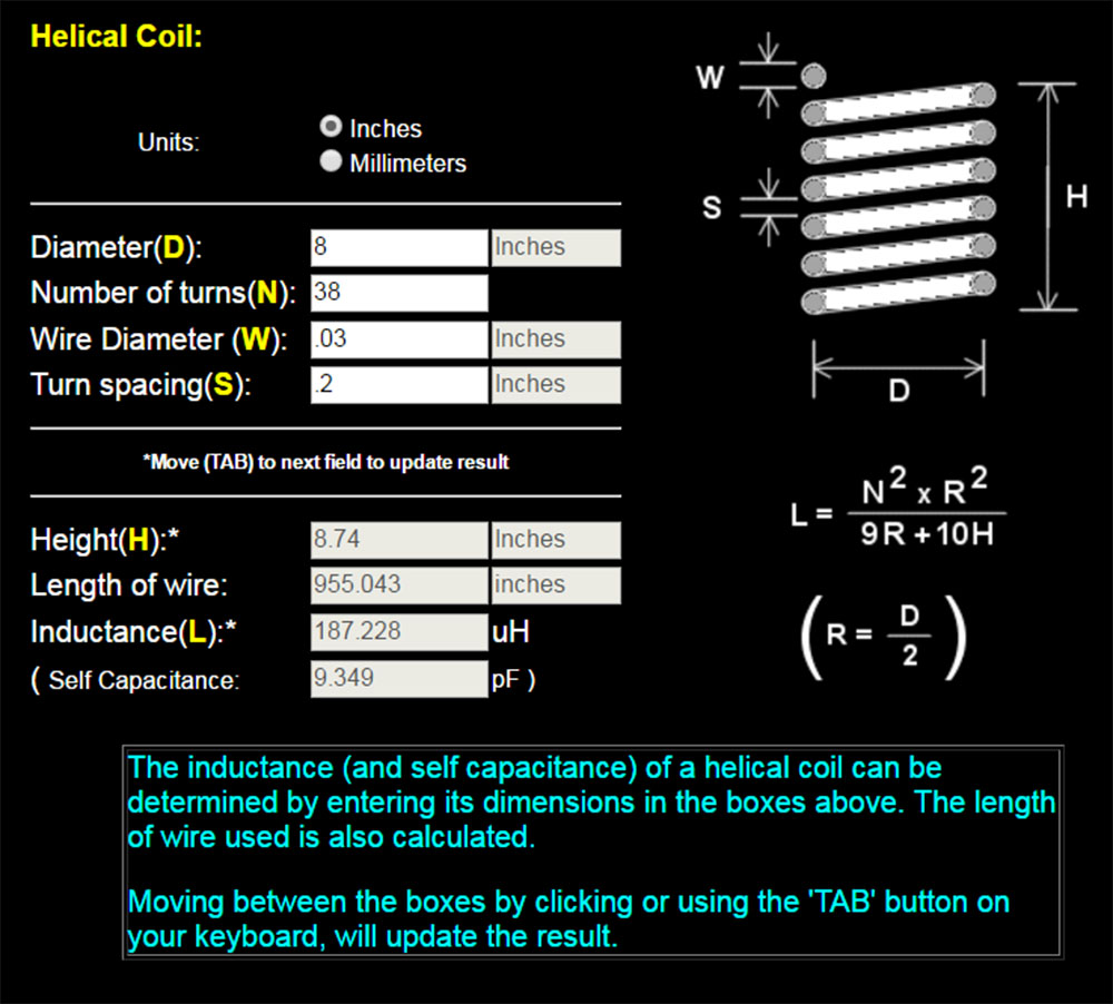


    At least the site gives you the coil length in inches.


    Originally posted by Wistiti View Post
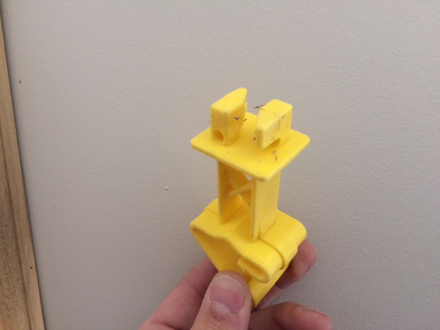
    For the ant. Insulator i think to use electric fence insulators see the photo


    These insulators will be good for a replication. Not too sure how they will perform if you add a voltage multiplier.


    What part of the world are you located in and what is your elevation above sea level?

    Leave a comment:


  • Wistiti
    replied
    Originally posted by soundiceuk View Post
    I bet you could wind it by hand within an hour and still have a cup of coffee.
    Hahaha!
    Thanks Paul for the reply but I'm not mean long in time but in length of wire... for ordering some hv wire! my English is not always good as i want!
    But i may take the time to take a coffee wile winding on the core!!!

    For the ant. Insulator i think to use electric fence insulators see the photo
    Attached Files

    Leave a comment:


  • soundiceuk
    replied
    Originally posted by Wistiti View Post
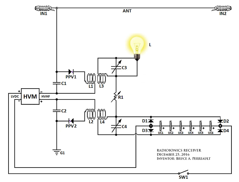
    Have you an idea how long it take to wind the 2 hv coil "L1, L2".( I refer to the V 7.0.0 schematic)
    I bet you could wind it by hand within an hour and still have a cup of coffee.

    Originally posted by Wistiti View Post
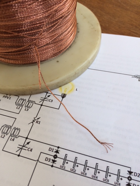
    I have another question if you dare; the only bare copper wire I have under hand is a multi strand one see the photo. Do you recommend me to use it for the antenna?


    Yeah that cable will work for an antenna. Make sure you use HV insulators.

    Leave a comment:


  • tswift
    replied
    As long as it's bare copper then I think it will work, I don't know why it wouldn't. Actually in some ways the braided stuff might be superior, I had a lot of problems with the wire wanting to kink and tangle as I was trying to pull it.

    Leave a comment:


  • Wistiti
    replied
    Ok guys, will not use coax. thank you for the reply; I will have to order some hv cable...
    Have you an idea how long it take to wind the 2 hv coil "L1, L2".( I refer to the V 7.0.0 schematic)

    I have another question if you dare; the only bare copper wire I have under hand is a multi strand one see the photo. Do you recommend me to use it for the antenna?
    Attached Files

    Leave a comment:


  • tswift
    replied
    Yes, I wouldn't use coax and expect good results. I thought seriously about it too, but if you ground the outer shield and just use the center conducter you will most likely defeat the effects we are trying to see. If you leave the outer shield floating then it will be at nearly the same voltage as the center conductor due to capacitive coupling, and then the only insulation between turns is the thinner outer jacket, not the thick foam middle. Under some circumstances you can indeed get away with using coax as HV wire, but not when you're trying to wind a coil with it. As interconnect wire it might do OK up to about 10 KV. I did some research and unless you have special coax, most people agree about 10 KV is all it's good for (and maybe not even that).

    I built my first coil out of enamel magnet wire, some of which is actually rated 10KV or more. But even that really isn't adequate here. As Soundiceuk said, in later versions of the device the voltage gets ramped up by use of an HV multiplier. Unless you want to buy more wire later and redo it all over again, the only real solution is to go ahead and bite the bullet and invest in genuine quality HV wire. It's hard to find the good stuff at a decent price, but I found an ebay seller in the US who deals by the name "hvforless". He has wire for under $1.00 per foot if you buy enough quantity. My wire should be here next week....

    Leave a comment:


  • soundiceuk
    replied
    http://www.energeticforum.com/renewa...-true-362.html

    Personally I believe it is probably the best page to start.

    Using that cable isn't the way forward.

    Mwtj got the previous circuit to work using a 15-20KV high voltage module and the 1KV HV wire was on its limits.

    Some 30KV or higher HV wire is recommended.

    Using a 370KV voltage multipler 30KV HV wire is on its limits. This is because of little to no current from the high voltage module.

    Leave a comment:


  • Wistiti
    replied
    Hey guys, I don't have hv insulate wire for the L1. Do you think I can use coax cable??

    Leave a comment:


  • Wistiti
    replied
    Originally posted by soundiceuk View Post

    There is a hidden gem in the PDF below.

    Excluding Tswift, Mwtj, or Serendipitor who will be the first one to spot it and post here?

    https://www.dropbox.com/s/jgh1zawik4...7.0.0.pdf?dl=0

    Happy hunting!
    I guest the composition of the "PPV" (2 thermoelectric dissimilar metal couple)...

    It is interesting to use a spakgap this way...!

    Leave a comment:


  • Wistiti
    replied
    Hi tswift.
    Thanks for your reply. Yes i have already played with the Don's device and like many other have no outstanding result with it as it suppose to be... Maybe I have not give so much time on it and jump on others project...

    I have also build some hv project and have already some parts to start with.

    As I understand your post, the pdf is not a guaranteed of success if it followed "by the book". Builders have to play with it to make it work correctly cause there are many factor involve in. (Above the see level, tuning for resonance, configuration of the antenna, ect....) That's what I will do with the low skill I have on the Don's stuff right now. I will start by doing my homework and reading some post back of what you guys already do on this "Radioionic receiver"

    I may have some more question laters...

    Leave a comment:


  • tswift
    replied
    The Story So Far....

    For those just joining us, here's a quick summary of the situation so far. One of us (soundiceuk) is a spokesman and contact person for another person, someone who personally knew Don Smith over a period of some years and was in a position to observe and learn from him, and discover how much of what Don claimed was hot air and how much was real. This person has also continued their own research and appears to be considerably advanced beyond all the rest of us in radiant energy research.

    Recently three of us (Serendipitor, Mwtj, and myself) agreed to undertake independent replications to prove the concepts and to publicly demonstrate whether the information being presented is for real. In return for spending our own money on parts and our own time for no compensation, we were given a few of the proprietary details needed to build the initial version of the device as specified. Experimenters who are already familiar with radiant energy type circuits and especially anything having to do with Don Smith will find the circuits very familiar. The terminology regarding "ions" is a bit different but make no mistake we are all talking about continuing applications of Tesla's radiant energy patents and discoveries and how to improve the circuits with the components available now in the modern era.

    So far Mwtj has had unqualified success and the other two of us are still tweaking. Even with significant experience in electronics in general and much time spent experimenting with radiant energy circuits, this is still not a "slam-dunk" project where you just put all the pieces together in one completely specified way and it works right the first time. But the evidence so far suggests that it works as claimed, and hopefully more evidence is coming soon.

    More people are now jumping on board, because for those of us who have been researching for a long time, this looks like the most genuine, most promising lead in years. I am not in a position to know or to tell very much more than anyone else other than the researcher in whose footsteps we are now following. You should thank him and be grateful that he is willing to share with the rest of us. Most of the requisite parts can be obtained from the usual sources of high voltage experimenting parts. Some things you will have to fabricate yourself. If you've been experimenting for a while you probably already have a good many parts on hand that will be useful.

    Leave a comment:


  • Wistiti
    replied
    Wow! Really interesting device guys!
    I have just finish reading the pdf. Thank's to you for sharing.

    I will take the time to read some page back of this tread to learn more on it (can someone point me where it start?)

    Im interested in building it. can you share where you buy all your part for it? Specially the air cap... it seem a bit expensive... maybe building one is not so hard.

    Again thank you for sharing!

    Leave a comment:


  • radioionics
    replied
    CIRCUIT BUILD v7.0.0

    Please let soundiceuk know if you spot any problems with this latest circuit. He will assist you the best he can.

    Best Regards, Bruce
    Attached Files

    Leave a comment:


  • soundiceuk
    replied


    TODAYS RELEASE

    December 29, 2016


    This release is to encourage replication. Please post any perceived design flaws and share your validation results.


    -Bruce

    ________________________________________________

    The is LOTS happening in the background. This is getting REALLY exciting!


    There is a hidden gem in the PDF below.

    Excluding Tswift, Mwtj, or Serendipitor who will be the first one to spot it and post here?

    https://www.dropbox.com/s/jgh1zawik4...7.0.0.pdf?dl=0

    Happy hunting!

    Leave a comment:


  • soundiceuk
    replied
    If tswift was to do it the other way around using the green wire as negative HV output, then both sides of C1 would be connected through the common ground in the unit as he had number 5 wire from the front of the panel of PVM12 to G.
    Last edited by soundiceuk; 12-29-2016, 06:40 PM.

    Leave a comment:

Working...
X