Announcement

Collapse
No announcement yet.

Donald Smith Devices too good to be true

Collapse
X
 
  • Filter
  • Time
  • Show
Clear All
new posts

  • med.3012
    replied
    Originally posted by tswift View Post
    I must say I'm surprised with everyone here. A long-time forum member comes on with claims that he knows more about this technology than we do and nobody is interested or considers it worth their time to check it out?

    don't be surprised ! a lots of great inventors lived within us and they are dead now ( peace for them ) maybe they didn't had the time to give everything to us but do we listened carefully to what they said ?

    believe me there's a lots of racism in the internet and of course a lots of stupidity ! Don Smith said it clearly ! Brain washed !
    Leave a comment:


  • tswift
    replied
    Serendipitor,

    Welcome to the party. We're all on the same journey here, Bruce knows more than Paul, who knows more than me. I'm just following along based on Bruce's publication and a few private hints. If you contact Paul, he will tell you some more important details. With a ham radio background (me too) and some experience with Don Smith style building/experiments this should be relatively familiar territory.

    Most of your antenna questions are the same ones I had. Think Beverage antenna. For sure we are not dealing with just conventional EM or this wouldn't necessarily make sense. I had the same idea about the flat plate collector or even larger diameter wire, but apparently that doesn't matter in this context.

    About the PPV, I think it is essentially just a specialized modified spark gap. A conventional spark gap, perhaps with some modifications, should be enough to get started.

    And the supercaps, if you have studied Don Smith he often talked about capacitors being the receivers of radiant energy (he used several different terms). There is a paper (the "Ambient Energy Generator") where he says outright that the energy collected is proportional to the size of the capacitors and mentions supercaps. I assume that for the best effects these are necessary.

    It is at one and the same time an advantage and challenge to be familiar with conventional electrical engineering, circuits, and radio. We are dealing with the realm of the unconventional where some of the normal rules may not apply but it's not immediately clear which ones. I am just building according to instructions received so far and seeing where we go from here.

    Leave a comment:


  • serendipitor
    replied
    I guess I might just join the party, as I have most of what is needed on hand from past experiments. I'm a long time radio enthusiast so I have wires and grounds already, and some high voltage broadcast transmitter parts to use. Some comments and questions about the circuit:

    * I wonder about the antenna, which is approximately 1/4 wavelength at 500kHz, but will vary widely depending on height and soil conditions. An antenna modeling program shows the impedance of the antenna to be very low, just a few ohms. I don't know enough about the PPV, but I would hope that there is isolation from the very high impedance of L1 and C2 in resonance. Since this is apparently a spiky, nonlinear circuit, it is perhaps not relevant to match to the antenna in a conventional E/M sense. Also, my experience with RF transformers like this would say that C3 is probably extra. One side of the L1-L2 couple affects the other such that the whole is resonated with C2, and C3 would so strongly depend on C2 that it could be eliminated. The transformer ought to be ringing more or less continuously, so is operating in the conventional linear domain, as far as I can tell.

    * A long wire as shown, low to the ground, with tens of kilovolts DC on it, is going to need an observer while in use. I would like to know more about the performance with height, as just a few meters higher, like the power lines, would be much safer. Anything that can come in contact with people or animals is not practical.

    * Given this I wonder what the real requirement of the antenna portion is. If it is drawing ions towards it, then would not surface area be more to the point, as shown in Tesla's flat plate collectors? I guess only experiment will tell.

    * Is there any data to indicate performance versus DC voltage on the antenna? I would guess it to be more or less linear, but maybe there is some sort of threshold. I have my doubts about putting very high voltage (>30kV) on something out in the weather (especially in rainy areas) as the need for extreme insulators becomes a limitation.

    * What are possible alternatives to the PPV component that could give some sort of "foot in the door" testing? I would like to see something interesting before sending $100 off to Bruce. Is he actively making these valves now? One thing I would like to see is the waveform across D5. What are people using at this point? I am not familiar with fast recovery diodes at this voltage level, but would be able to try a string of lower voltage units which are on hand. Certainly the current demands are tiny, given the 10Meg resistor in series.

    * I can't see that super caps are a real necessity. Either the circuit is making enough to send back to the HVM, or it is not. More capacity does not change things, unless there is a *highly* intermittent nature to the impulses. Conventional caps should do OK, if this is going to yield watts of power over time.

    Best of luck in all your experiments. I have looked into Bruce's Yahoo group, but there does not seem to be much in the way of excitement there. As soon as I get any results one way or the other, I will post them here.
    Attached Files

    Leave a comment:


  • tswift
    replied
    OK, back to the actual research. Here is some of the experimenting I did yesterday. First, after tuning the L1 primary coil to resonance at roughly 500 KHz, I checked the capacitance of the C1 tuning capacitor to find the resonant value. Given the inductance of the coil I was expecting about 100 pF, and sure enough I measured 93 pF:
    https://gateway.ipfs.io/ipfs/QmUu3QE...j/IMG_1533.JPG

    Then I grabbed one of the many coils from my bin-o-previous-projects, an 80-turn coil on a 2: cardboard coil form. I can try using this as an L2 coil without having to wind a new one, at least for starters. It measures just under 80 uH:
    https://gateway.ipfs.io/ipfs/QmUu3QE...j/IMG_1534.JPG

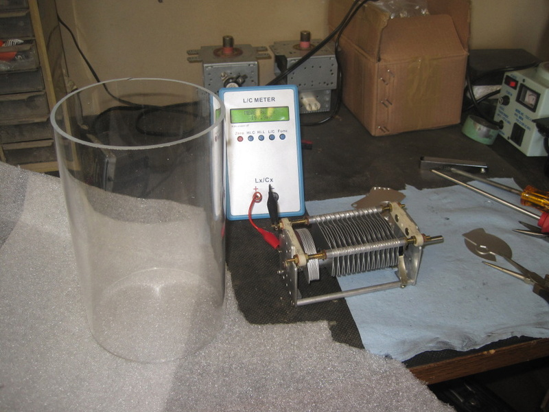
    Now we will need a C2 tuning capacitor to bring the L2 coil into the same resonance as the L1 coil. Since the inductance of L2 is much less than L1, the capacitance has to be correspondingly more. The good news is that the voltage on the L2 side is much less, so we don't need a high-voltage tuning cap here with wide gaps between the plates. I had this one handy, it's one of the common "365 pF" radio tuning caps. It has two sections, and they can be paralleled for twice the capacitance, as seen in this picture. The maximum capacitance with the plates fully meshed is about 760 pF tested:
    https://gateway.ipfs.io/ipfs/QmUu3QE...j/IMG_1536.JPG

    And the minimum capacitance is about 40 pF. Note that this cheap L/C meter is probably not all that accurate, but it seems to do an adequate job for this purpose.
    https://gateway.ipfs.io/ipfs/QmUu3QE...j/IMG_1537.JPG

    Comparing the two variable capacitors, C1 and C2, you can see at a glance the difference in the spacing between the plates. The C1 cap looks somewhat odd because the one I bought off of ebay wasn't the model I was expecting and I had to rebuild it by doubling up the little spacers between the plates to get them wide enough. Hopefully the C1 cap should handle several kilovolts without arcing over between the plates now.
    https://gateway.ipfs.io/ipfs/QmUu3QE...j/IMG_1539.JPG

    Here's the arrangement for testing for resonance using a function generator. The L2 and C2 coils are in parallel, being driven by the function generator through a 10K ohm resistor. This produces a fairly sharp voltage peak right at resonance as you tune the function generator. This is because of the high impedance of the parallel LC tank circuit formed by L2 and C2. At exact resonance, the capacitive reactance and inductive reactance exactly cancel and it appears as a high resistance, proportional to the tuned circuit Q.
    https://gateway.ipfs.io/ipfs/QmUu3QE...j/IMG_1540.JPG

    Here is the scope and function generator being used to tune for resonance. With the C2 cap fully closed (maximum capacitance) the resonant frequency is right about 680 KHz. To tune down to 500 KHz to match the L1/C1 side, we will need to add a fixed capacitor in parallel with C2. I haven't yet calculated how much this needs to be, but probably around 500 pF as a first guess.
    https://gateway.ipfs.io/ipfs/QmUu3QE...j/IMG_1541.JPG

    Here is a short video of how to tune for resonance with a function generator. Watch as I change the cap holding the function generator frequency constant, and then change the frequency holding the capacitance constant. This is where a digital oscilloscope makes your life much easier because it will calculate and display the frequency in real time, fairly accurately. A separate frequency counter would also work for this. It would also be possible to connect the high voltage supply and spark gap to the L2/C2 combo like I did with the L1/C1 combo and read the ring frequency off of the scope, it should exactly match the results obtained this way with the function generator.
    https://gateway.ipfs.io/ipfs/QmUu3QEhtVec3ADaXCvamrZEvijBLbwb9P34cYWKoWgacj/MVI_1544.MP4

    Edit: I tried to include the pictures inline but they were too large to display correctly. I included them as links instead, you'll have to open each one to load and then you can see it either full size or scaled as you choose. Hopefully I got all these IPFS links correct, they just link directly to files on my computer. I apologize for the large file sizes, but I think about how much time I have spent studying pictures and videos by other researchers and I always wished the pictures were clearer so you could see every detail. I shoot them in full 10MP camera resolution for archival and now you can see them that way too. Using IPFS you can also download them to your computer easily, there are several different ways to do it. Learn more about IPFS.
    Last edited by tswift; 11-18-2016, 04:53 PM. Reason: fix video link

    Leave a comment:


  • tswift
    replied
    Well, while we're on the "moon" subject, let me introduce you to a friend of mine.... IPFS, the interplanetary file system. No, I'm not kidding, some geeks actually dreamed this up and coded it, it's for real. Technically, it's a replacement transport for HTTP for the internet. It uses peer-to-peer, distributed technology from bittorrent to replicate content everywhere and it's robust even over slow or high-latency internet links (thus the "interplanetary" part... you could browse the web from Mars and it would work, albeit slowly at first). IPFS lets you publish content once and have it be replicated everywhere. For instance, I can publish my whole "pictures" directory on IPFS with a simple link and everyone can new view the original full resolution pictures without me having to upload them to dropbox or the forum. Even better, when they are viewed by someone through IPFS, the content gets replicated and future viewers can access either the original or the copy, speeding up access. The more viewers, the faster it runs and the more robust it is against anything from internet problems, to server outages, to censorship. Can anyone in this forum think of why we might have a censorship problem? How many times have you gone to look at an overunity-related youtube video and you get the "oh sorry, this video isn't available any more" message? If we start publishing really sensitive information then this forum will get taken offline in a hurry. Anything from DDOS attacks against the server, to penetration and hacking, to pulling the domain name. Just ask Kim Dotcom how many dirty tricks can and will be applied. We need a more robust solution, and this is the best one I've found yet. First there was Napster, and the record industry shut it down and sued it out of existence. Then there were copycats with incrementally better technology and they succeeded for a short time before also being shut down. Now we have bittorrent and it can't be shut down, not without turning off the internet entirely. IPFS is like that: distributed, peer-to-peer, highly resilient and censorship resistant. There is no easy way to stop it.

    So here's the link, browse to your heart's content. Everything in here is for public distribution, Creative Commons CC-BY license applies. Through the magic of IPFS over a VPN I can serve this folder to everyone, everywhere and still not expose my IP address. Why use dropbox when you can BE dropbox?

    https://gateway.ipfs.io/ipfs/QmUu3QE...9P34cYWKoWgacj

    Even better, of course, is to download and install IPFS yourself. Then your computer can act as its own proxy instead of using the master gateway at gateway.ipfs.io. This saves server load for them and is more resilient, because the master gateway is just a server that could itself be DDOS'd or hacked offline. If you have a local installation of ipfs, then an HTTP link like this will also work:

    http://localhost:8080/ipfs/QmUu3QEht...9P34cYWKoWgacj

    It's quite easy to install and configure, I did it in 15 minutes yesterday. Just go to ipfs.io to get started, and help us change the world.

    Leave a comment:


  • soundiceuk
    replied
    I don't know the answer to your question but I will try and find out.

    I do know that Bruce started his research by looking for an energy source to power a spaceship.

    I'm in an unusual position in my life as some of the stuff he has shared with me in confidence is blowing my mind!

    One of the patents he recently shared with me confirms there was another inventor that knew of the technology in the same period as Tesla.

    In USA too.

    We need to release this technology slowly so I can't say who it is.

    These disclosures are going to surpass anything that you could even believe imaginable.

    Looks like the great Tom Swift is going to get to the moon 1st publicly!

    Leave a comment:


  • tswift
    replied
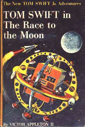
    Well, the name is a pseudonym, as I presume you know already.... I actually wasn't trying to be that subtle but I guess I'm a few years older than most of the audience here. Probably few of you grew up reading these wonderful pulp fiction stories, but I did:


    Oddly enough, I have a few things in common with ol' Tom. Not the least of which is that I'm working on this real-life technology, which as I've discussed in another thread, should have antigravity potential. Tom's fictional spaceship "Challenger", pictured above, used "repelatron" rays emitted from the dishes for space propulsion. Close enough, I suppose. Has Bruce ever mentioned anything to you about gravitic effects related to these devices? I suspect they probably also produce the endothermic "cold electricity" effect when operating.

    Leave a comment:


  • soundiceuk
    replied
    You're doing a great job and I'm just going to throw this into the mix but what do you would happen if you did a pancake coil for L2?

    It's a reverse tesla coil isn't it?

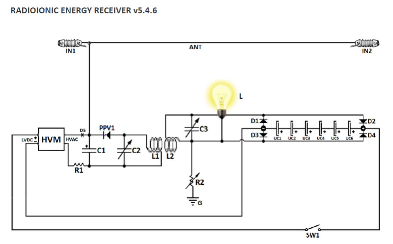
    It makes lightning in the high voltage, high frequency plasma diode. PPV

    Anyone that builds to the same stage as tswift they will be given those proprietary details for personal private research and development.

    So far there are builders that I know in USA, Russia, Holland and UK.

    I think tswift is going to be the 1st to show a replication because the facebook page has only 59 likes so far.... is growing.

    This is so much more attractive than regular solar.

    tswift you're doing a GREAT job. They don't call you "swift" for nothing hey?

    Leave a comment:


  • tswift
    replied
    Today's experimenting: put the L1 coil into the test circuit and check the frequency. The design frequency is 500 KHz, with a tuning range encompassing both higher and lower frequencies. As built with the variable capacitor I have the tuning range is approximately 300 KHz - 1000 KHz. Here some pictures and a scope shot of the test circuit tuned for 500 KHz (approximately).
    Attached Files

    Leave a comment:


  • tswift
    replied
    Yes, I noticed that too. When I first saw the schematic I immediately noticed it might as well be a Don Smith circuit but for two things: first, the antenna, and second, the potentiometer in the ground connection. Many of Don's schematics have this "variable element" in the grounding but are never specific as to what it is or what range of value. Is it a capacitor, a resistor, or an inductor? Or some combination? Is it 1 ohm or 1M ohm? The fact that it was deliberately left vague makes me think that it's important. You can see what will happen to the circuit if the grounding is left off: the whole secondary side of the circuit will float at a voltage that will vary with the ambient electric field, primarily due to the L1 coil and the antenna. On the other hand, connecting it to ground through a zero or very low resistance will not allow it to float at all. Being able to adjust the ground resistance will cause the amount of voltage bounce of the whole secondary side of the circuit to vary between these two extremes. Obviously there is no output transformer shown in this schematic as in Don's (when he shows it), but if the circuit principle is essentially the same then it should be possible to drive a high-power output from a 12V inverter attached to the cap bank, for instance. The problem in this case would be the non-ground-referenced potential of the whole secondary side of the L1/L2 coils, most inverters have the input and output grounds in common. Interestingly, the little Radio Shack inverter Don used does NOT have the input and output grounds tied together. I have one and I have verified that this is the case. The amount of voltage isolation between the primary and secondary sides of the inverter will also have to withstand the full degree of voltage float of the circuit, which I am not sure how much that is likely to be. Probably several hundred volts and possibly several thousand volts. Most off-the-shelf equipment is not going to like that. The PVM12 itself is also unique in this regard: it has separate grounds for the drive circuitry and the HV transformer. Normal practice is to tie them together but it's designed so you can separate them too.

    Leave a comment:


  • tesluh
    replied
    Will be interesting to see how it goes, I saw that schematic on another forum, many elements in common with Don's devices.

    Leave a comment:


  • tswift
    replied
    Well, I'm gratified that we have at least one very sharp-eyed reader! Yes, it is indeed my workbench and equipment; I emailed these to Paul privately, for public distribution. As I sort-of alluded to previously, I have joined forces with Paul (and by extension, Bruce) to do a full replication of this design. You will be able to follow along with me as I build and test it in near real time. If it fails, you will know. If it succeeds, you will also know. Some parts of Bruce's designs are still proprietary and not yet for full public distribution but there is plenty that can be shown. The principles should be quite familiar to anyone who has already been working on their own Don Smith experiments, in my case I already had many of the parts on hand such as the PVM12 and the high-speed high voltage diodes. I had to invest in the doorknob cap, a high voltage tunable capacitor and the coil winding supplies, probably around $100 out of pocket so far. If Bruce really has been continuing Don's research and is that far ahead of the rest of us, I consider it money and time well spent to educate myself and start catching up with the current state of the art. Even if for some reason this fails I will have learned a great deal more and have a greater selection of useful equipment for experimenting, so in no case is it really wasted.

    Leave a comment:


  • tesluh
    replied
    Originally posted by tswift View Post
    I must say I'm surprised with everyone here. A long-time forum member comes on with claims that he knows more about this technology than we do and nobody is interested or considers it worth their time to check it out? Funny, I thought science was about open-minded scepticism. If you are not willing to at least investigate overunity claims and learn more, then why are you even here? Personally, I am in contact with Paul and actively following up and learning more.
    tswift, isn't that your pvm12 power supply sitting on your blue table top with your old pc fan spark-gap in the photos above? Does Soundiceuk have the exact same equipment and bench as you? Something strange going on here...

    Leave a comment:


  • soundiceuk
    replied
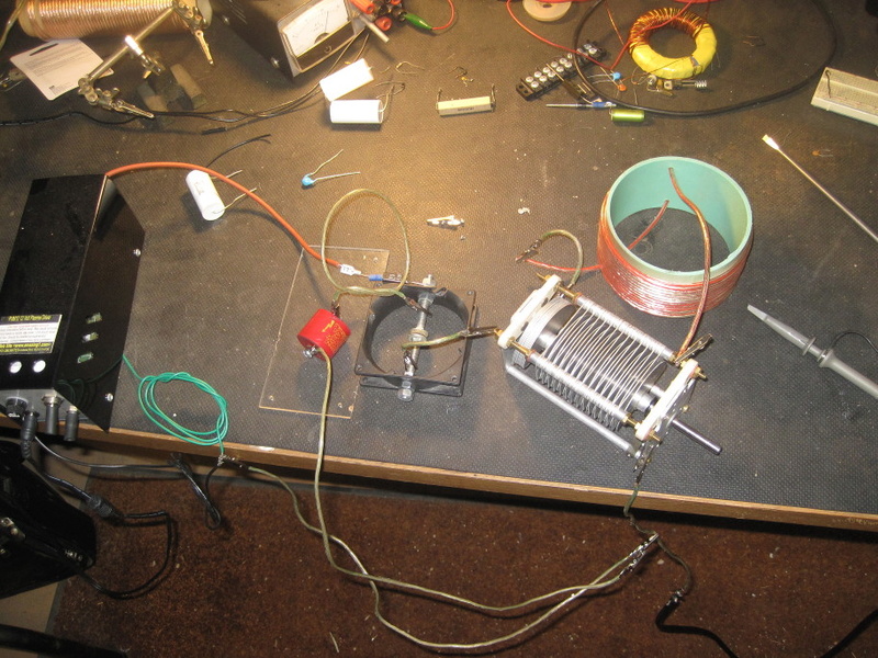
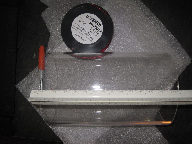
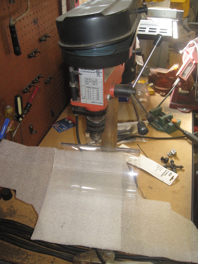
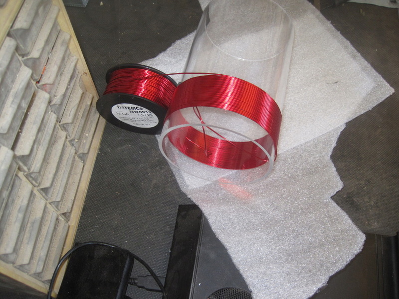
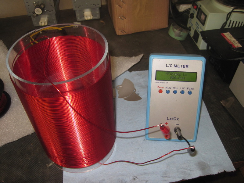
    He are some photos of a preliminary test with an existing coil that was lying around and then making a 1000uH 117 turn coil on 5" acrylic tube to be resonant at 500khz.


    Video 1: https://www.dropbox.com/s/wi5co7lw6j..._1523.mp4?dl=0

    Leave a comment:


  • soundiceuk
    replied
    Thanks for that Solarlab. Here is a reply from the modern Tesla.

    "Aether is a word that someone uses when they don't really know exactly where energy comes from.

    The quote should read; The negatively and positively charged ion sea will be referred to as 'The Sea of IONS,' in order to distinguish it from Electrical or electromagnetic currents of energy."


    -Bruce
    Last edited by soundiceuk; 12-27-2016, 10:38 PM.

    Leave a comment:

Working...
X