If this is your first visit, be sure to
check out the FAQ by clicking the
link above. You may have to register
before you can post: click the register link above to proceed. To start viewing messages,
select the forum that you want to visit from the selection below.
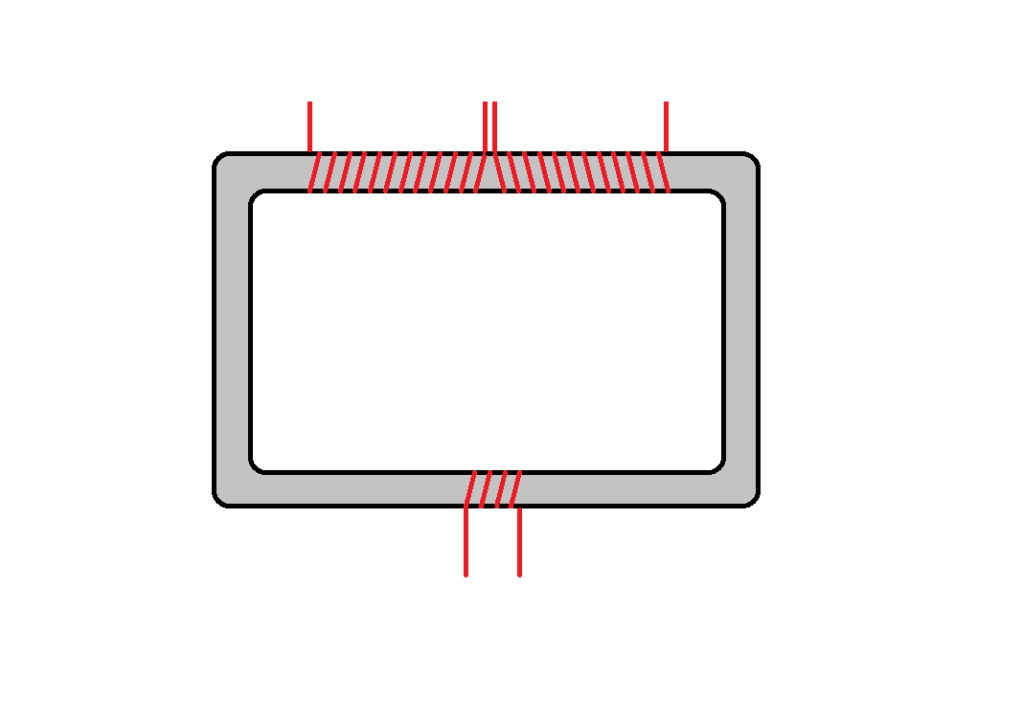
I think the secondary's need to be larger gauge wire, think transformer, the voltage coming from your nst is high, you need to step it down, therefore the primary should be small gauge and the secondary's large gauge, bring the voltage down and amps up.
I would think all the wire should be of substantial gauge. Consider for a moment what is happening when you discharge a cap into an inductor - it basically converts voltage to amperage which creates a large magnetic field then we stop the flow violently.
A hydraulic analogy - picture a tube that has thousands of tiny holes in it, the holes are small enough that under normal flow and pressure it will not leak. So we open the valve to start the flow and once it's up to speed we slam the valve shut - all that momentum/energy has to dissipate somehow so the pressure exceeds the tiny holes ability to hold the fluid in and it sprays everywhere into the environment. Maybe a good analogy for ionic wind as well.
Since the transformation from the capacitive discharge is primarily amperage leaving only a remnant of voltage remaining that flows in the coil you need to step it up to a point where it is once again useable, only this time we have introduced a larger current flow in the secondary. "the condensor method of magnification"
Notice on most of Dons circuits the output (from the secondary coil on) is basically a transformer isolated buck converter which, once again, enhances current flow and decreases voltage.
I believe another misnomer is what resonance is...
Nice analogy, but I think that magnetic field is free At least if we break at correct moment keeping resonance. Think about it that way :
if we have a superconductor (omit just the power required to cool it down) then the initial DC current put into a closed loop coil would produce magnetic field indefinitely. Our only problem is that we cannot keep resonance or rather we are learned wrong methods , but this simple superconductor example teaches us that magnetic field is free.
Nice analogy, but I think that magnetic field is free At least if we break at correct moment keeping resonance. Think about it that way :
if we have a superconductor (omit just the power required to cool it down) then the initial DC current put into a closed loop coil would produce magnetic field indefinitely. Our only problem is that we cannot keep resonance or rather we are learned wrong methods , but this simple superconductor example teaches us that magnetic field is free.
Since we don't have superconductor components to work with we have to continue dealing with the resistive forces. We can, however, make our coils with a wire size that will reduce resistance as much as physically possible, this would also reduce our input requirement as well.
I like the idea of superconductors but unfortunately I doubt I'll be able to afford such a thing in my lifetime - could be wrong - I'll stay open to the possibility in any case.
Still it's not free, you have to put the initial energy into the system to get it oscillating, as well, if you load that coil it will dampen the oscillations just as resistance does. Finding the perfect open system to isolate the input from the output might be in the same category as peak efficiency or the best combination of both.
A series LC circuit, at resonance where xL and xC are equal there is no reactive component so theoretically current can rise without limit. It behaves as if it were a short circuit, the resistance in the coils act as a current limiter... sort of a pseudo superconductor with a restriction.
A parallel LC is just the opposite, when at resonance xL=xC and Z becomes a resistance of infinite value not allowing current to pass through it, operating like an open circuit. These can circulate a large amount of current based on L and C values (large C and small L = high current ). These can have currents circulating that are so high that the resistance of L is sufficient enough for the coil to burn up.
The condition of the parallel LC is what we want to occur on the input side - very small input with high currents circulating ( recycling ). This requires precise tuning, any variation over or under resonance results in a large input requirement... The series LC would be most efficient on the output side in an open loop.
I believe she made a difference, but Im not sure she had a working device if so why keep changing the schematics but nevertheless she did boost this thread.
But you must think for yourself, study the magnetic and electric fields as well as the electronics they have to work together.
dave
WOW! Have you got some links for more details. Never seen this. It is completely off my notions. I want to learn more!
No links for this. They are the result of my experiments. Treat it as the research material it is. I posted it so that others could replicate it with scope shots.
Over to you guys an gals.
According to Zilano you need spark gap and resonance to achieve OU. I've been studying her posts very hard and she gave us a lot of food for thought. She didn't want to give the secrets away on a silver platter either. I'm convinced that she had working devices. She/He was a very sharp individual indeed. Zilano did say that Don left a very big secret in plain view without bringing it to our attention. She said he said he had shared all we need right before our eyes but he didn't elaborate what he was referring to and/or where specifically he left the secret. David Fine
Between work and family duties I have been diligently exploring the entire ideas of Don and Zilano by examining the components.I have cross referenced ideas with other researchers who have nothing to do with overunity.
I have compiled the data and I am more convinced than ever that Zilano was onto something.Take for example the work done by MIT with wireless electricity.Resonance is clearly demonstrated.The concept of the harvest coil (ala Zilano) is also seen.These guys actually built Don's central transmitter device.Just that they were not interested in actually finding out if several LEDS placed in the right spot at resonance would draw equal amounts of energy without loading the transmitter coil.Boy the things I could do if I had their equipment...
Again another set of wireless researchers have mentioned the tremendous power available at resonance.
I have also downloaded and read through several patents for RESONANT TRANSFORMERS.
Presently I am musing on the latest schematics for the CCFL resonant transformer.
The MRA device and the Shwartz Device also reeks of Don and Zilano....
Now this entire thread plus Patrick Kelly's pdf,the Utkin doc,Dynatrons designs,joule theif concepts,the inductively coupled crystal radio, and my own conclusions drawn have given my a very clear idea of how to make the device.
The fact is I am limited by funds and have to get half yearly as import duties in my country are over 43%... sigh.But I will get there.What I am aiming at just now is to build my own resonant transformer and establish to my satisfaction the actions of resonance.
I have concluded that:
(1.) Variable capacitors are the way to go.So serious fine tuning can be done.
(2.) Yup, a spark gap is necessary.(Gas ionisation, radiation effects and resonance,Laser beam creation is worth reading.)
(3.) I would use coils that are strickly air core, since PVC is said to interfere with the energy fields at high frequencies.
(4.) single core non insulated wire only for the L1 and L2,I am assuming they will be more efficient at absorbing stuff.(Don has a "naked" secondary and so did Dynatron.
I could go on and on, but I have kept and continue to keep an open mind.Looking in several other places for info but the moment of truth will be when I finally "MAKE IT" Thanks ZZZZZZ.You ROCK!
I am still following every square inch of this forum and making observations and notes.
One of the reasons why I quit contributing. I knew a lot of the schematics that were posted here would not work just by looking at them, but I tried them just to be sure. I know how you feel. In my last video you could see by the reflection on the wood that I was lighting a bulb brighter using high voltage and high frequency then straight DC. I didn't scream OU because I used that output and reduced the voltage/frequency and measured the amps/volts and it was not OU.
As you have stated before, you can light a bulb brighter with HV/HF, but that does not mean you have OU. Just a more efficient way of doing what we have always done. You don't need a degree in science or physics, you just need the tools and the will to be able to measure and study. I have seen some of your experiments and you definitely know what you are doing. I am skeptical about over unity, but that does not mean there is not energy all around us to be tapped that the public has not found yet.
When someone accurately measures input vs output and can show more out then in, or something running by itself, then I will try it also. It doesn't mean over unity, it just means the energy is coming from somewhere we don't understand yet. Keep up the good work Farmhand.
ZZZZ certainly introduced some radical circuits, I dont know if she powered her house with a working unit or not but... the sections of her scematics that Ive tried certainly perform. As for one look at the circuits and "I could see It couldn't work !" Well as I work on my humble replication I find myself extracting power from what is essentually a short circuit, well we've all seen it done on video regarding a so called Tesla Hair pin circuit but in this case its dynamic,
when and if each stage is tuned in regard to a standing wave the whole foundation of electrical/electronic engineering is drastically changed. Regardless of anyones expertese one glance prooves nothing, In fact all standard training is about as much use as “Tits on a kipper”
There was such a determined attempt to quickly remove all ZZZZs posts from all forums I personally believe it to contain very important information. I'm sure very soon we'll owe Slovenia a big thank you for being vigilent enough to catch the destruction, rescue and archive the posts and information.
As I work on these circuits the effort to force myself to do something that I know should not work and then does makes me feel nausious, It really is that bad!
So please dont be so determined to lampoon ZZZZ just because we can't comprehend … Yet!.
Even the circuit which she made a lot of use of the so called “Avramenko's plug “ RESONANCE EFFECTS FOR EVERYONE TO SHARE test 1 - YouTube is an enigma . So before you “glance at a circuit”
and proclaim loudly”It cant work” start with these three common components and try and see what is happening and how what so clearly “shouldn't work” so demostrably does .. Do you see Avramenko's plug here? Avramenko's Free Electrons Pump v1.0 by Jean-Louis Naudin
see the Avramenko plugs in this very important Russian circuit?
so stay focused DELAMORTO / FreeEnergyLT / FreeEnergyLT but dont be in too much hurry to write ZZZZ off
I recommend ignoring and boycotting the newly reactivated old Don L Smith thread. The competition is posting there and they don't want you to have a working Don Smith device. They want you to believe that they are credible and that the old science that Don Smith and Tesla prescribed to was not credible. That's a no brainer. I wonder who I'd vote for? Don Smith & Tesla were extremely bright guys and they knew how to make free electricity. Have fun; keep your mind positive to the old Tesla science; and boycott the other site so you don't contaminate your mind. Don't waste your time there!!
Im sorry but to boycott any thread just becouse he doesnt agree with you is very close minded, we are all in this together, and together we will find the answers.
Every detail must be studied, even if you just study the plasma coming from the tesla coil and notice they are multiple and not just one stream.
Farmhand has done some cool experiments, think for yourself and study everyone's work.
dave
Comment