Announcement

Collapse
No announcement yet.

Donald Smith Devices too good to be true

Collapse
X
 
  • Filter
  • Time
  • Show
Clear All
new posts

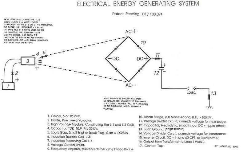
  • very cool, but im confused...

    Originally posted by T-1000 View Post
    http://www.overunity.com/7679/selfru.../attach/95834/ has step up transformer missing to Pentod's Anode
    The measurments:
    1) On Anode it is 315 V pulsed DC, approx 50mA.
    2) The Tr2 and Tr1 are 50Hz 10W transformers, taking 50Hz from the grid. The purpose of them is 50Hz signal source, not power.
    3) The Pentod Anode is connected to step up transformer. That transformer connects to parallel of Tr2 and 50Hz phase must match.
    4) It was not possible to take precise Amp reading on Tr2, so lets say, it is 10W as maximum per transformer
    5) Pendode heating element takes more than 15 Watts when heating and 12W when in working condition.
    6) The 100W halogen is attached as load.
    7) The secondary of Tesla coil is split into two parts: 1st is 1/4 of second coil length. The distance between them on tube is 3.5 cm.

    Also, this circuit uses general idea of RF equipment but does not operate in conventional way. There is ionization on Tesla coil going on and there are coil-capacitors inside of Tesla Coil. The Tesla Coil is tunned to 800kHz resonant frequency.
    So here is question: is it possible to light and overheat 100W halogen with 16W power input..?

    The answer most likely will be shown when you repeat this circuit...

    P.S.> The longer secondary coil part is winded into opposite direction in regards to first 1/4 length coil. The receiving Tesla coil (inside of transmitting coil) is winded opposite to transmitting Tesla coil. Also you can have receiving Tesla coil outside of transmitting Tesla coil.
    what is the source? i get the signal concept "not for power"

    L30 joins L31 by..?, its the dotted ceramic cap looking ones?

    the bottom of L32, one end is not connected?

    6n36C figure block, is a relay?

    thanks for posting
    In the beginner's mind, there are many possibilities.
    In the expert's mind there are few.
    -Shunryu Suzuki

    Comment


    • Parallel Gap

      Originally posted by soundiceuk View Post
      Isn't the capacitor supposed to be in parallel and the spark gap in series for OU bell waveform?
      I tried this but did not work. I'm should change my capacitors and see what happens. Another thing I'm suspecting my pipe connection is with a 2 bolts and maybe charge is going to ground from my wood board.

      Comment


      • Originally posted by soundiceuk View Post

        Did anyone else notice that in those photo's Don is NOT using a full wave bridge
        rectifier ? He is using two half wave rectifiers (which is different from the drawing )
        and he has the center tap connected directly to the DC cap negative.

        There are a few items missing as well.

        So by my reckoning the device in the photo works at about 260 Khz or so and
        half wave rectifies the two out of phase HV outputs from each end into the
        HV caps (the coils appear to be both wound CW) the center tap should be
        grounded as is the HV DC cap negative Like in the drawing) making two out of
        phase 1/4 wave Tesla type coils at resonance.

        Solved !

        Plenty of distractions there but if we look closely we can see it. Oppositely
        wound ends of the L2 will work differently. They should be the same as if
        made from one coil, as Don say's in one of his video's.

        Then we make AC from the HV caps. Fun part. Well that's my Plan and my
        take on it. Just thought I would share that.

        Cheers

        Comment


        • Originally posted by Farmhand View Post
          Did anyone else notice that in those photo's Don is NOT using a full wave bridge
          rectifier ? He is using two half wave rectifiers (which is different from the drawing )
          and he has the center tap connected directly to the DC cap negative.

          There are a few items missing as well.

          So by my reckoning the device in the photo works at about 260 Khz or so and
          half wave rectifies the two out of phase HV outputs from each end into the
          HV caps (the coils appear to be both wound CW) the center tap should be
          grounded as is the HV DC cap negative Like in the drawing) making two out of
          phase 1/4 wave Tesla type coils at resonance.

          Solved !

          Plenty of distractions there but if we look closely we can see it. Oppositely
          wound ends of the L2 will work differently. They should be the same as if
          made from one coil, as Don say's in one of his video's.

          Then we make AC from the HV caps. Fun part. Well that's my Plan and my
          take on it. Just thought I would share that.

          Cheers
          The L2 can be wound the same way and the + and - swap.

          The outer ends become earth and the centre positive.

          Don figured out the coil is not needed at all.

          The HV source, then capacitor in parallel and a gas discharge tube in series on one line, full wave recitifer in parallel with voltage divide then electrolytic capacitor to smooth out rippled DC and then the load, then earth to ground.


          Also I forgot to say as I was so tired when I posted last night.

          The AEG is made from Barium Titanate

          BARIUM TITANATE TRANSFORMER


          Barium titanate - Wikipedia, the free encyclopedia

          I think this is Tesla's air battery. Ahem....... or should I say air capacitor.

          THIS COPIES EXACTLY HOW THE EARTH IS BEHAVING AS A SUPER CAPACITOR SUCKING IN COMIC RAYS!!!!


          Also I will be happy to make a picture showing what the components are. Will do that ASAP.
          Last edited by soundiceuk; 02-26-2012, 11:13 AM.

          Comment


          • Originally posted by a.king21 View Post
            Do you think this is the circuit Don meant?

            I have attatched an Oliver Lodge experiment from the 1890's in which he found that a spark gap was more than duplicated at the point of a reflected wave. An earth ground acts in a similar way in that it cases a standing wave. Lodge found that the length of wire had to be tuned to the wavelength of the spark gap input.

            C'mon GUYS and gals... This has got to be a big clue...
            Help me here....
            I'm not sure, I'm still in a bit of spin having unearthed loads of Don's stuff that I didn't expect to find.

            Oh yeah the other circuit without coil:

            Comment


            • Originally posted by Haan
              .
              Load that pic into photoshop or some other similar software. Then you can zoom, stretch, filter, use all the effects to see whats going on plus all the small writing on the components. Ive done this with some of the stan meyers photos before. Amazing the amount of info i got by doing this. If you know how to use sketchup and can find a known reference point in the photo (i.e the mains plug or thickness of the board) you can get it to calculate the size of any other part of the picture, not done this myself but my pal has so i know its possible.
              Last edited by philly b; 06-05-2012, 06:40 PM.

              Comment


              • Originally posted by Farmhand View Post
                Did anyone else notice that in those photo's Don is NOT using a full wave bridge
                rectifier ? He is using two half wave rectifiers (which is different from the drawing )
                and he has the center tap connected directly to the DC cap negative.
                ...
                Sorry, have the schematic you refer to not at hand.
                As far as I rememeber there is an earth connection before and behind the rectifier. Thus two diodes are short circuited by the earth connections and can be omitted.
                Experts spend hours a day in order to question their doing while others stopped thinking feeling they were professionals.

                Comment


                • Originally posted by soundiceuk View Post
                  ....


                  ...
                  1.
                  There are capacitors with 3 terminals! Does enybody know how thery are connected? Do we have here the 3 plate setup involved?

                  2.
                  The screw terminals on bottom side are not connected. Are these the earth connections?
                  Experts spend hours a day in order to question their doing while others stopped thinking feeling they were professionals.

                  Comment


                  • Originally posted by Farmhand View Post
                    Did anyone else notice that in those photo's Don is NOT using a full wave bridge
                    rectifier ? He is using two half wave rectifiers (which is different from the drawing )
                    and he has the center tap connected directly to the DC cap negative.

                    There are a few items missing as well.

                    So by my reckoning the device in the photo works at about 260 Khz or so and
                    half wave rectifies the two out of phase HV outputs from each end into the
                    HV caps (the coils appear to be both wound CW) the center tap should be
                    grounded as is the HV DC cap negative Like in the drawing) making two out of
                    phase 1/4 wave Tesla type coils at resonance.

                    Solved !

                    Plenty of distractions there but if we look closely we can see it. Oppositely
                    wound ends of the L2 will work differently. They should be the same as if
                    made from one coil, as Don say's in one of his video's.

                    Then we make AC from the HV caps. Fun part. Well that's my Plan and my
                    take on it. Just thought I would share that.

                    Cheers
                    His output as I see it is a transformer isolated full wave buck converter... DC-DC power converter http://ecee.colorado.edu/~rwe/papers/Encyc.pdf
                    Last edited by dragon; 10-24-2014, 12:03 AM.

                    Comment


                    • Originally posted by soundiceuk View Post

                      There is a coil in the NST. And Don's setup is like a big resonant NST.

                      Wont this setup just spark the load until the capacitor # 12 is charged then not
                      much will happen ? Unless the capacitor #12 is discharged, then as it charges the
                      current to ground will spark the load again. Try it and see.

                      I can set it up and test it but I think I know what will happen.

                      To me that looks like Don's drawing modified by someone else.

                      Cheers

                      Comment


                      • Frequency

                        Is anybody else trying to run in the Mhz range? I thought that was the sweet spot for power capture. Excuse my ignorance if I am wrong.
                        Thanks

                        Comment


                        • The site Index for /papers has a useful source Haan.

                          Farmhand, the diagrams are made slightly puzzling on purpose as people who think they are going to get rich by protecting their IP all seem to do this, so no one can copy. It's like giving a TV set with a part purposely broken.

                          Just as well that out of all the inventors that ever came up with any OU device, Don left us pictures, videos, demostrations, books etc.

                          I think he wanted us to figure it out ourselves when we are ready. Just like Tesla destroyed the magnifying transmitter himself because he knew people we not ready for that, as we didn't understand the forces that we are now learning about.

                          Because the diagram isn't drawn in an electronics standard it becomes hard to see the wood through the trees.

                          The part that confuses you has confused me also. Only I think I have been looking at it a lot longer than you, I'm sure someone else would have spotted it too if they had been looking as long as I did. However we need to move things along as fast as possible.


                          No one told me this I just worked it out.

                          This only just clicked in my head tonight folks.

                          Once the capacitor / coil or just capacitor arrangement goes into magnetic resonance the circuit turns super conductive (negative resistance).

                          The Negative 4 in the diagram is earth ground.

                          The two HV outputs of the NST both should have diodes (the large heatsinks are hiding them in the picture) and are joined together after the diodes to create a full wave on one side of the capacitor. The earth ground connection on the other side of the capacitor.

                          The frequency and duty matched to put the capacitor/s into magnetic resonance kicking out massive voltage and amperage.

                          Jees! This could power a cruise ship with the right design.

                          Notice the isolation transformer is centre tapped.
                          That to me means maybe this is best way to get 100% efficiency from a core.
                          The CC and CCW isn't important as the + and - just swaps.

                          I don't even think it matters whether everything is wound CW or CCW. Not sure on that one.

                          Remember what Don said "THE MAGNETIC COUNTERPART OF AMPERAGE AND RESISTIVITY ARE USED BY SPECIAL INTEREST IN THEIR EFFORT’S AT HIDING THE TRUE SOURCE OF ALL ENERGY.

                          TWO INEXCUSABLE OMISSIONS ARE WRITTEN OUT OF THE TEXT BOOKS. FIRSTLY, IN MAGNETIC SYSTEMS POTENTIAL AND AMPERAGE ARE EQUAL. MAGNETIC FLUX SPEED IS GREATER THAN VISIBLE LIGHT SPEED.

                          SECONDLY, THE MAGNETIC EQUIVALENT OF NEGATIVE RESISTANCE IS HIDDEN, BEING THE INCREASE OF MAGNETIC PERMEABILITY. MEASUREMENT METHODS USED BY PHYSICS ARE HIGHLY SUSPECT."

                          The resonance creates a charge pump.

                          The earth grounds allow the magnetic current to flow and although its an open circuit electrically, it's not magnetically.

                          Comment


                          • Originally posted by Seeker2011 View Post
                            Is anybody else trying to run in the Mhz range? I thought that was the sweet spot for power capture. Excuse my ignorance if I am wrong.
                            Thanks
                            The power isn't being captured. It's being pumped from the ground through a rectifier then modulated and voltage controlled then back to ground.

                            Did you know the neutral in your house is an earth ground!

                            Comment


                            • Originally posted by Farmhand View Post
                              There is a coil in the NST. And Don's setup is like a big resonant NST.

                              Wont this setup just spark the load until the capacitor # 12 is charged then not
                              much will happen ? Unless the capacitor #12 is discharged, then as it charges the
                              current to ground will spark the load again. Try it and see.

                              I can set it up and test it but I think I know what will happen.

                              To me that looks like Don's drawing modified by someone else.

                              Cheers
                              This is Don's drawing modified like his email message:
                              Bruce,
                              The Device in question is the same one I demonstrated at the Tesla convention 5 years ago that caused such a ruckus. The Inverter circuit already has the necessary components required. Disconnect the main diode bridge negative output from the output capacitor bank. Then hook the disconnected negative capacitor to a separate circuit which powers the load and into an adjustable earth grounding. At this point you are tapped into the universal source of endless energy. There is a simple way which does not require the inverter. Any how let me know and will work it out. You already have all the required parts as does most everyone else.

                              Wipe out 6, 7 and 8 and connect the diode bridge where #6 was. Number one is a tritium battery with half life of 11 years, small size. The output appears to be pulsating DC but is actually high frequency which explains the ill matched light bulbs.

                              The plasma tube device dipole with the capacitor plates at right angle get's greater than 65,000 times the input. The energy has to be already there to be seen. Special Interest try to discredit this type of observation. Since this is energy from the ambient, is high frequency, use a diode bridge with the negative plate as an open circuit. The capacitor transformer opens the door to an endless source of useful energy. I successfully built the device here described. The operation will be Tuesday.
                              Regards, D.S.
                              09-02-2004

                              Comment


                              • Originally posted by soundiceuk View Post
                                The power isn't being captured. It's being pumped from the ground through a rectifier then modulated and voltage controlled then back to ground.

                                Did you know the neutral in your house is an earth ground!
                                Captured or pumped, ZZZZ said Mhz range was better. Yes?

                                Comment

                                Working...
                                X