Announcement

Collapse
No announcement yet.

Donald Smith Devices too good to be true

Collapse
X
 
  • Filter
  • Time
  • Show
Clear All
new posts

  • thanks man

    Originally posted by soundiceuk View Post
    Blue Serge and Nolanmenne are both using the HV ouputs with HV diodes with the the gas discharge tube in parallel after the diodes.

    The capacitor is in series with the L1 coil and they are both in parallel with the spark gap.

    My observation (without experiment yet) is that this is only one capacitor off a hairpin circuit which as we know forces resonance and makes cold electricity / scalar / LMD.

    We are trying to make a mirrored primary correct?


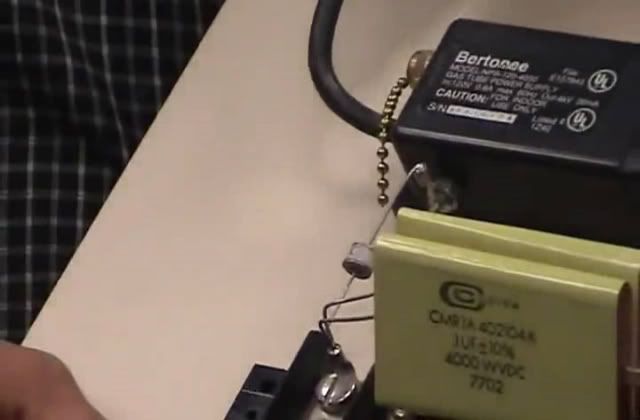
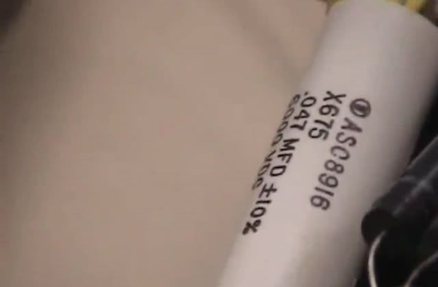
    Here is a close up of the L2 capacitor.


    After listening to all of Don's videos that I can find here is what I heard.

    The L1 capacitors were ordered from Cornell Dubilier and were rated at 10kv and 0.5uf each.

    Contact Us - Directory By Department - CDE.com


    However the capacitors in the picture are manufactured by Custom Electronics.

    How to Contact Us | Custom Electronics, Inc.

    The are rated at 0.1uf each and rated at 4000v.


    It is very clear to me that Don wanted to disclose everything after his dreams of getting this to market were squashed again and again by special interests.

    He had friends in high places and clearly they let him build from his imagination many different devices until he laid his last golden egg.

    This must have been on the proviso that he never disclosed exactly how to build a device.

    Just like Tesla and in his footsteps, Don scattered the truth right, just like a puzzle right before our eyes. Even saying 'the smart ones will figure it out'. He blantantly used a different manufacturers capacitors because knew someone would pick up on it eventually.

    Now I'm very happy to be proved right or wrong. I just wanted to share my observation.


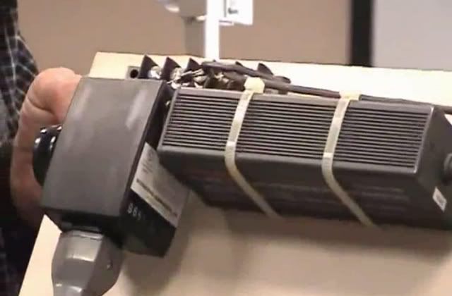
    Here are some more photos that you may like to see.


    Don also said the NST was custom manufactured by Bertonee.

    The diodes are 25kv and were custom manufactured by Varo.


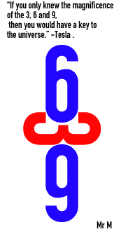
    The secret is in this. The coil is the 3 and the CW and CCW are the 6 and 9.

    Don also said look at diodes, capacitors and coils. The voltage is in the length and the amperage is in the width.


    If the capacitor is in parallel with both negative lines, does that mean it is in series because they are both negative???

    Once we debunk the main board Don shows we will move forward very quickly.
    If Don had the NST custom made then would having the primaries wound in CW and CCW make any difference?

    I believe it would as I keep blowing 3 amp fuses in my driver when I'm experimenting.

    I assume that if the primary windings were in CW CCW fashion then there wouldn't be any back emf.....???
    wow thanks for that, a lot of work went into that reply

    i still am not sure of the cap values and/or arrangement tho, i have tried and didnt have much luck,,, BUT i believe it is viable.

    and about the 369, it truely is the answer to "the universe"

    well,,, the 9 ... then 3 and 6 are...9 as well

    here you go if you havent seen

    Randy Powell - Intro to Vortex Math - Part 2 - YouTube

    and it makes sense to relate the coils to natural phoenomena, but i still wonder about the direction of the turns, only experimenting will tell. problem is i have...and still dont know whats best LOL
    In the beginner's mind, there are many possibilities.
    In the expert's mind there are few.
    -Shunryu Suzuki

    Comment


    • quick questions

      Originally posted by joefr View Post
      Here is the video:
      Don Smith Zilano Test 2 - YouTube

      JoeFR
      Hi joefr,

      Thanks for your work and diligence.

      Some questions though. I can see you are in doors what ground connection are you using. Also keep room ventilated due to discharge from gap. also what is the voltage rating of the secondary resonant caps.

      Regards

      Comment


      • Hi abdlquadri

        Thanks for your work and diligence.


        Some questions though. I can see you are in doors what ground connection are you using. Also keep room ventilated due to discharge from gap. also what is the voltage rating of the secondary resonant caps.

        In this test I was not using ground connection. I am waiting for warmer weather to make two real ground connections. I noticed the ozone production from spark gap i this test is very minimal to test where I used kacher circuit with tesla coil.
        The single cap in secondary resonant cap is 0.22uF 1250Volts and I can combine them in any parralel series configuration to get values from 18nF to 440nF.

        JoeFR
        Last edited by joefr; 03-06-2012, 09:48 AM.

        Comment


        • Originally posted by joefr View Post
          Hi abdlquadri
          In this test I was not using ground connection. I am waiting for warmer weather to make two real ground connections. I noticed the ozone production from spark gap i this test is very minimal to test where I used kacher circuit with tesla coil.
          The single cap in secondary resonant cap is 0.22uF 1250Volts and I can combine them in any parralel series configuration to get values from 18nF to 440nF.

          JoeFR
          Thanks alot

          Comment


          • Pay attention to EVERY word Don Smith used.....

            Don Says "The plasma tube device dipole with the capacitor plates at right angle get's greater than 65,000 times the input. The energy has to be already there to be seen. Special Interest try to discredit this type of observation. Since this is energy from the ambient, is high frequency, use a diode bridge with the negative plate as an open circuit. The capacitor transformer opens the door to an endless source of useful energy. I successfully built the device here described. The operation will be Tuesday.
            Regards, D.S."

            "Energy has to be already there" - what does it mean ? It could mean that energy is there from "somewhere" but only Don can tap it ?
            OR
            I think it means that energy has to be "created" in plasma and capacitor plates at right angle is the way to tap it without disturbing

            Comment


            • Originally posted by dragon View Post
              It would appear to me that your input is 12.? volt at .5 amp. Your saying that each bulb requires .100 amp to operate so your series circuit would have .100 through it but the voltage is increased to 60 or a total out of 6 watts. If the bulbs were parallel then the amp requirement would increase to .5 amps but not in series. 6 watts in 6 watts out that's more efficient than most devices where you would typically see 6 watts in and 5 watts out, around 80%.

              So the question would be, how to decrease input and not alter the output.
              As always, well said

              Also, when i turn it up to 1 amp, (12 watts), the output is "impressive... most impressive" -(D.Vader
              And what do you make of the cw cw, would i get more out still?

              But still i think there is merit to the cw cw on the double helices board, after the vid i was adjusting position, and got a noticable drop in output when either L2 was removed, so they are both definitely contributing.

              Oh god, il have to wind an 80 turn ccw i guess lol
              In the beginner's mind, there are many possibilities.
              In the expert's mind there are few.
              -Shunryu Suzuki

              Comment


              • Zilano, many thanks for the information you provide.

                Please can you clear up the mystery surrounding the start of the circuit?

                In most of the circuits available (even ones that Slovenia gathered from you) the HV source, spark gap and diodes are incorrectly placed.

                A number of them had the diodes backwards facing towards the NST.

                What is the correct start of the circuit?

                This is where most electronics people get confused and don't bother attempting a replication.

                If we can correct all the circuit diagrams that are circulating the web with the right components alot more people will replicate the device.

                Many thanks.

                Comment


                • Originally posted by Gedfire View Post
                  Hello All,

                  I read with interest an article on converting silver and copper to gold using "photon resonance".

                  Later down in the article I saw where they said that the stuff will only work if the experimenters were in an area of magnetic anomalies.

                  They then showed a magnetic map of the places in the US.Much to my amazement those maps were very similar to the ones spoken about by Don in one of his interviews!

                  So I went back and watched Don's video again and sure enough he was referring to the said maps.

                  The implications may indicate that in order to get some of Don's devices to work properly your location maybe necessary.

                  Attached are screen grabs of such a map.The purples are areas of high negative potential.This is the first time I am seeing these maps outside of Don's interviews.

                  Is it possible that this possibly overlooked aspect of Don's work may have contributed to some of the failures?

                  Soundiceuk,you rock man! Those Don pics and your analysis are priceless.I like where you (and others) have said Don gave us a puzzle to figure out.Maybe the final piece could be the importance of location...

                  Any extra info and location and the Don/Zilano devices function are welcome.

                  Still learning.

                  Ged
                  Thanks for bringing this up Ged. I was trying to recall the government web site where those magnetic maps are at. I do believe this can be a big factor for certain types of energy devices. Knowing where Don lived I'm going to check to see how his area looks on those maps if I can find the site again. Some people probably think Joe Champion is nuts but he seems to have a lot of research time spent on all that and I can see why his info might need to be kept mostly 'under the radar'. I've read through nearly all his info and I think he's got something that has potential for free energy also. I think it might be interesting to check where Steven Marks TPU units were demonstrated also on these maps. And welcome back Zilano
                  Last edited by ewizard; 03-06-2012, 08:05 PM.
                  There is no important work, there are only a series of moments to demonstrate your mastery and impeccability. Quote from Almine

                  Comment


                  • Originally posted by dragon View Post
                    That would be one very good way to reduce input... ( patent # 609,250 for those interested).
                    cool thanks for this
                    In the beginner's mind, there are many possibilities.
                    In the expert's mind there are few.
                    -Shunryu Suzuki

                    Comment


                    • Originally posted by zilano
                      @ all

                      good to see development of all the doers thinkers and critics- without whom we cudnt have progressed so far. congrats blue serge and joefr for the contribution and enthusiasm. advice is----> follow Don.

                      @ mr. clean follow don. cw cw and hv cap storage. u wont see actual power until after trafo. cap storage is dc which has to be converted to ac and fed to step down trafo. only then u can measure input output in true sense. rest not till u get past stepdown trafo.


                      rgds

                      zzzz
                      Ok, on to the next step then , and thanks for the rotary 60 hz idea

                      I really like the igbts too, we'll see
                      In the beginner's mind, there are many possibilities.
                      In the expert's mind there are few.
                      -Shunryu Suzuki

                      Comment


                      • Hi Zilano Thanks

                        good to see development of all the doers thinkers and critics- without whom we cudnt have progressed so far. congrats blue serge and joefr for the contribution and enthusiasm. advice is----> follow Don.

                        Is your advice to use thick low turn primary coil and thin wire many turns CW CW secondary coil with center tap?

                        Then match primary LC and secondary LC resonant frequency and put energy from secondary LC in high voltage storage caps and then use stepdown transformer to make useful energy?

                        JoeFR
                        Last edited by joefr; 03-06-2012, 09:16 PM.

                        Comment


                        • Originally posted by mr.clean View Post
                          Ok, on to the next step then , and thanks for the rotary 60 hz idea

                          I really like the igbts too, we'll see
                          It is very unfortunate to stick with 50/60Hz frequency. N. Tesla always used 20 000+ Hz for his circuits then stepped down frequency in output circuits...
                          Also one thing about primary of Tesla coil needs to be understood:
                          When you got quarter wave of frequency wave length, you get split of voltage in one secondary coil end and current in another. The wire length defines resonant frequency wave length.

                          And of course, the current goes into/out of earth over capacitive load...

                          And finally, when you mix two frequencies where lower frequency current rides resonant frequency voltage, the power of the system gets increased reaction with strong echoes from ambient. On the output the low frequency carrier sine wave with resonant frequency wave inside is seen.
                          For more information you can look in N. Tesla ball lightning production notes and experiment results: Corum Ball lightning

                          P.S. Those words may be useless until you actually will do experiment and see yourself.

                          Comment


                          • Don Joe Magnetic Maps References

                            Originally posted by ewizard View Post
                            Thanks for bringing this up Ged. I was trying to recall the government web site where those magnetic maps are at. I do believe this can be a big factor for certain types of energy devices. Knowing where Don lived I'm going to check to see how his area looks on those maps if I can find the site again. Some people probably think Joe Champion is nuts but he seems to have a lot of research time spent on all that and I can see why his info might need to be kept mostly 'under the radar'. I've read through nearly all his info and I think he's got something that has potential for free energy also. I think it might be interesting to check where Steven Marks TPU units were demonstrated also on these maps. And welcome back Zilano
                            Zilano welcome back! and I see you have hit the ground running as usual.Words can't say enough...


                            Ewizard the magnetic anomalies map referred to Don and Joe Champion is called : EMAG2: Earth Magnetic Anomaly Grid (2-arc-minute resolution)

                            It is found here: Earth Magnetic Anomaly Grid and
                            EMAG2: Earth Magnetic Anomaly Grid

                            Here is the link to the article he wrote.
                            January 29

                            There is also a plug in for Google earth hence you can check to see Steven Marks and the others location.

                            Patrick Kelly, it would be good to see if there are any links to the others in your pdf who have reported success.Kapandanze,Moray, etc.

                            Just to say that Joe in his article did find some correlation between location and the successes of the people using his Transmutation Techniques.

                            I noticed the business of resonance was key to transmutation in his theories.

                            Zilano and others have echoed, follow Don and maybe these special locations mentioned by Don may be a big factor.

                            Remember the info that places like water falls and grotto being areas of high negative ion concentrations? Wonder if waterfalls correlate to the strong purple areas on the magnetic field maps? Could we try for Niagara Falls eh?


                            Hey Zilano, what do you think about this location theory? Could you check your location for us please.Just let us know if you fall in the strong purple area.

                            Thanks.

                            Best regards,
                            Ged

                            Comment


                            • Negative Ions

                              Hello All,

                              Just after posting the above I went Googling and found this:

                              Locations of Negative Ions

                              High concentration of negative ions can be found in a variety of natural environments. These include forests, mountains, waterfalls and beaches. In nature, negative ions are generated by lightening, sunlight, ocean waves and falling water. According to peakpureair.com, Niagara Falls is one of the highest natural producers of negative ions in the world.


                              Wow!

                              Natural Ways to Create Negative Ions | eHow.com

                              Read more: Natural Ways to Create Negative Ions | eHow.com Natural Ways to Create Negative Ions | eHow.com

                              Comment


                              • In addition from what I said before, here are some additional info:
                                http://home.dmv.com/~tbastian/files/balllite.txt

                                The most important part:

                                Parasitic oscillations, or circuits, within the main circuit were a source of danger from this cause [of ball lightning]. Points of resistance in the main circuit could result in minor oscillating circuits between terminals or between two points of resistance and these minor circuits would have a very much higher period of oscillation than the main circuit and could be set into oscillation by the main current of lower frequency.
                                Even when the principle oscillating circuit was adjusted for the greatest
                                efficiency of operation by the diminution of all sources of losses, the fireballs continued to occur, but these were due to stray high frequency charges from random earth currents.
                                From theses experences it became apparent that the fire balls resulted from the interaction of two frequencies, a stray higher frequency wave imposed on the lower frequency free oscillation of the main circuit.
                                As the free oscillation of the circuit builds up from the zero point to the quarter wave length node it passes through various rates of change. In a current of shorter wavelength the rates of change will be steeper. When the two currents react on each other the resultant complex will contain a wave in which there is an extremely steep rate of change, and for the briefest instant currents may move at a tremendous rate, at the rate of millions of horsepower.
                                This condition acts as a trigger which may cause the total energy of the powerful longer wave to be discharged in an infinitesmally small interval of time and at a proportionately tremendously great rate of energy movement which cannot confine itself to the metal circuit and is released into surrounding space with inconceivable violence.

                                Comment

                                Working...
                                X