If this is your first visit, be sure to
check out the FAQ by clicking the
link above. You may have to register
before you can post: click the register link above to proceed. To start viewing messages,
select the forum that you want to visit from the selection below.
Hi all.
Nice to see that the topic has geared around its scope.
@Boguslaw
Yep it is what I was looking for, the info you wanted to share with us all.
Thanks about that.
Thanks goes to Gedfire and Stoker_x1 too.
Now it becomes cleaner and cleaner, I mean the idea:
Don speaks about resonance and how much important it is, and suggests to us to arm ourselves
with a good RLC meter.
Tariel Kapanadze, also speaks about resonance and the importance of it.
Ghazanfar_Ali also speaks about getting and maintain resonance.
Nice work from all contributors.Many Thanks from me.
Best Regards.
<< BP Ultimate + Shell-V Power + Allies (opec) = the Ultimate Power Aligators to Suck People`s Blood !-! >>
Now it becomes cleaner and cleaner, I mean the idea:
Don speaks about resonance and how much important it is, and suggests to us to arm ourselves
with a good RLC meter.
Tariel Kapanadze, also speaks about resonance and the importance of it.
Ghazanfar_Ali also speaks about getting and maintain resonance.
Nice work from all contributors.Many Thanks from me.
Best Regards.
I don't know if it is true but towards the end of the Moray book 5th edition there is a mathematical derivation and statements to the effect that for OU effects to be found in resonance that R(squared)C must be less than 4L. Otherwise you end up with power robbing damped oscillations.
R(squared) - that would explain why an excellent low resistance ground is essential.
Also, a good old fashioned grid dip meter is an inexpensive, simple, and fairly precise real time method of detecting resonance when tuning in coils.
I had hoped to prove my point here and I think I did. Since my post there have been ten new posts. Two of those posts talked about work they were researching and Eight were about nothing. To date, this thread contains 5155 posts. That means with all things being equal, I would have had to read 4,124 posts that have nothing to do with the subject at hand. I think it is sad that I should have to read that many post having nothing to do with the subject.
Also, reading that people were deleting their posts is troublesome. Dave, I don’t have to delete my posts since I never posted from the beginning. I have always told my children “If you don’t have something good to say, then you shouldn’t say anything”.
I’m not keeping anything secret here. Everything you need to know was given to you by Don Smith, a very smart man who shared more than enough to help you succeed. If I were to add anything to the information he shared with the world, it might change wrongly how you understand something. I didn’t discover this device, he did. I followed his instructions and explanations and it works. I have nothing to add to this. There is nothing new I can tell you about. I took what Smith said, combined with my knowledge of electronics and my experiences gained from building blocking oscillators and thief’s and built his device. I made mistakes, corrected them and moved on. In the end it worked and the work it does is growing with each revision. It took me two weeks to see my first good results. If you don’t understand what Don Smith has said, then re-read what he has said like I did and eventually, you too will get it right.
Give you a break, well Dave, Give Me A Break, please.
Stoker your right my post was uncalled for, I usually dont poke my nose out like that, dont know what got into me.
I apologize and
I hope your device improves more everyday
share it with those around you
best wishes
dave
I don't know if it is true but towards the end of the Moray book 5th edition there is a mathematical derivation and statements to the effect that for OU effects to be found in resonance that R(squared)C must be less than 4L. Otherwise you end up with power robbing damped oscillations.
R(squared) - that would explain why an excellent low resistance ground is essential.
Also, a good old fashioned grid dip meter is an inexpensive, simple, and fairly precise real time method of detecting resonance when tuning in coils.
yes, no, maybe so?
Orion
The Daniel Cook patent also depicts a low resistance very high inductance coil and would confirm the R< sqrt(4L/C) theory - this was 15 years before tesla. Also shows the use of a 3 plate capacitor and later moray used a similar technique in his tubes.
Also, a good old fashioned grid dip meter is an inexpensive, simple, and fairly precise real time method of detecting resonance when tuning in coils.
Orion
Correction - A grid dip meter is not the right tool for the frequencies in use. A good RLC meter is definately needed. I remember now that in my long gone ham days I was tuning for a plate current dip. My apologies.
Primary L1 and L3 Feedback coil is 160mm in diameter
This is in my setup you just have to watch that feedback coil winding is not to close to secondary coil winding because a spark can jump.
This setup should work with any diameter of secondary coil you will just need to adjust position of L1 Primary coil and the turns of L3 feedback coil for best output.
Well there you (we) have it. stoker_x1 says he has a working Don Smith device. And he says it's all about resonance. The same thing I posted again here recently - saying Don was always pushing R-E-S-O-N-A-N-C-E. And he confirms that the 'Secret' Ghazanfar Ali gave us is correct. stoker_x1's statement regarding that might have been a little confusing unless you realize he was quoting Farmhand who was quoting bbem who was quoting Ghanzafar Ali. Yep it got a bit convoluted but this is precisely what he was saying - that Ghanzara Ali is correct. And again I'm going to choose to believe stoker_x1 is being honest here. So to me his info is a big boost. The only problem is it sounds like I'm going to have to actually engage my BRAIN. Actually think Well I knew there had to be a catch.
to power the first transformer - trlf1 ?
From there it's a matter of converting radiant energy to conventional current.
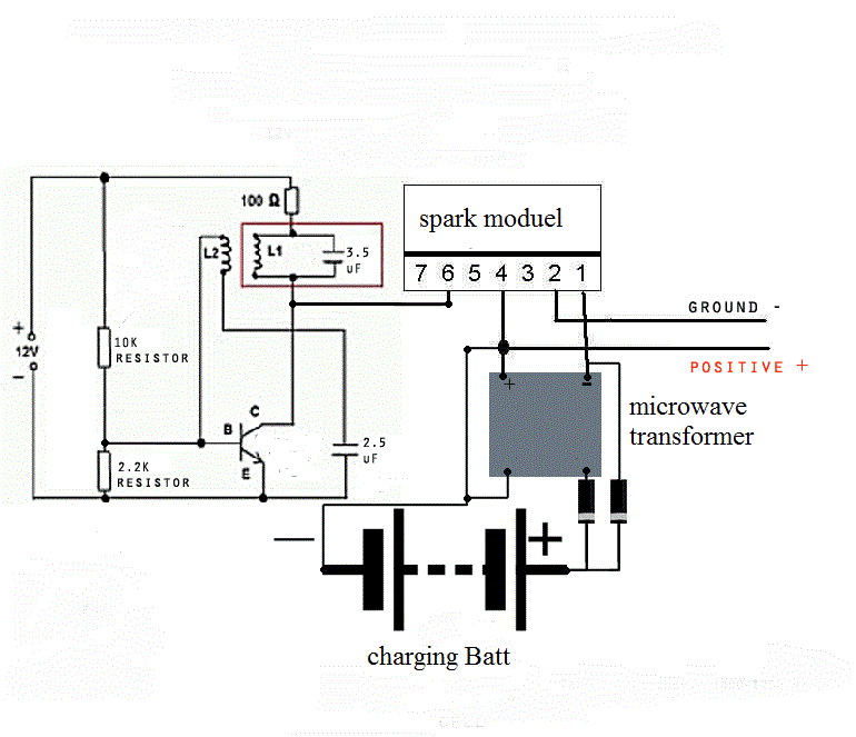
It includes instructions on how to build an impedence matching circuit that will automatically tune to resonance if used for making hydrogen or charging a battery. The circuit finds the absolute perfect frequency, and adjusts continuously depending upon the condition of the water or battery that you are charging. It is one of the only HHO pulse circuits that automatically finds the resonant frequency of a given WFC (water fuel cell).
You are a good fellow!! You are frustrated like the rest of us; read and studied a lot; to much information to keep up with and a lot of it is purposely tainted; and someone tells you they found the golden grail. It's normal to be a little testy when you are passionate like we are about getting your hands on a working DS device and someone says they have it but won't share the details. They just tell you to read some more. Most of us are read out but we will read and study till we do have this device ourselves.
Thanks Stoker for sharing that you do have a device and that the details are available in Don's written information!! It helps to keep us motivated and working.
Stoker your right my post was uncalled for, I usually dont poke my nose out like that, dont know what got into me.
I apologize and
I hope your device improves more everyday
share it with those around you
best wishes
dave
Let me say thank you first and congratulate all of you for starting to think again. I agree, there is a price to be paid for success.
Can this be done without all the gear? I don’t know, but for me it was the only way to find the right numbers. Finding the proper capacitors to smooth the circuits is not a simple matter. Knowing the inductance, resistance and capacitance of the circuits is required and once you know that and purchase the capacitors, then you need to know the new or adjusted frequency. That frequency will then be used throughout the device. Let me say this one more time, While building the device, you will find that the frequency will change with each newly added part. That is OK, as long as you understand that in the end, all three sections of the device must be in harmony. Remember, your final frequency will not be the one you started with most likely and it will not be the same as another tester doing the same build. When you understand the reasons for this, you will succeed. There is no set frequency, just resonation.
There are other issues that should be addressed. If you have read or listened to DS properly, you should recall that he would occasionally say that he could not tell us everything since there were commercial considerations regarding his device.
Then consider this: Everyone should know that he gave great detail to the 4 to 1 calculation for the L1 and L2 coils. In the videos he would always add his commercial considerations at that point after discussing the calculation. I always wondered what he was not saying. Moving forward in his presentations, while talking about one of his other designs he said something different. He said that the weight of the copper coiling material used must be 4 to 1. That struck me as not being the same thing as the length of wires being 4 to 1. It took time for me to realize that this is the method he chose for selecting the right wire to use in his coil designs. I purchased a two hundred dollar jeweler digital scale and then tested this idea. Wire manufacturer’s use different doping agents to create differing kinds of copper wire for different uses. When I started weighing same size wire I did find differences. The weight of the wire times the length of the wire determines the turns required to properly build L1 and L2. Don’t forget that once built, you must check frequency and then use proper capacitor across the circuit. Weight vs turns can produce a properly constructed resonate circuit, one that can almost work without the needed capacitor, but with the addition of an appropriate capacitor, it becomes perfect with no resistance. It will not get hot.
Also important is the need to address the length of wire between the high voltage source and the L1 coil. DS said that the length of wire between the two must be one fourth of the frequency. Again, the weight of the wire and gauge wire used must be carefully calculated as this too affects the frequency of the device.
I have made a couple of points here that you should consider and test. Don Smith was an expert in these matters and the two points made above were his way of building a perfect coil. When built his way, the selection of component parts became easier.
I hope this helps. There is no need for me to write a tutorial or further explain these matters since Don Smith has already done this in a much better way than I could ever do. Having said that, I’m done for now and hope you all succeed.
Thanks for great info. Can you please post a schematic of your working device.
I like to know the position of the spark gap and what you use for spark gap ( ordinary spark gap or GDT gass discharge tube - surge arrestors )
Can this be done without all the gear? I don’t know, but for me it was the only way to find the right numbers. Finding the proper capacitors to smooth the circuits is not a simple matter. Knowing the inductance, resistance and capacitance of the circuits is required and once you know that and purchase the capacitors, then you need to know the new or adjusted frequency. That frequency will then be used throughout the device. Let me say this one more time, While building the device, you will find that the frequency will change with each newly added part. That is OK, as long as you understand that in the end, all three sections of the device must be in harmony. Remember, your final frequency will not be the one you started with most likely and it will not be the same as another tester doing the same build. When you understand the reasons for this, you will succeed. There is no set frequency, just resonation.
sounds like you are describing a musical instrument
thank you again for all the info you provided .......much appreciated
“Signs and symbols rule the world, not words nor laws.” -Confucius.
Comment