Announcement

Collapse
No announcement yet.

Donald Smith Devices too good to be true

Collapse
X
 
  • Filter
  • Time
  • Show
Clear All
new posts

  • Originally posted by zilano View Post
    keep the cold end of ur hv coil earthed to prevent shocks!

    rgds
    ....
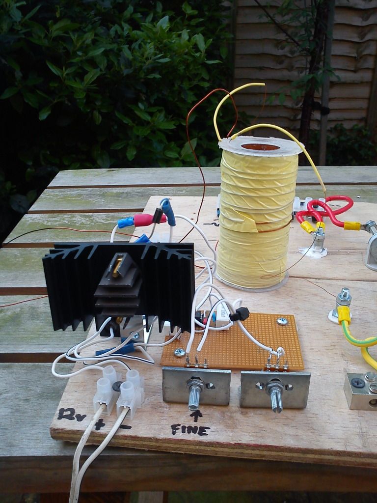
    I think they were still "live" even with the earth ground in place (the pic is not how I had it running, I had the coil on the right (reverse Tesla) disconnected, as it was just losing the sparks (obviously as it's not been tuned yet).

    I separated the LV side of things to a different board, like so......
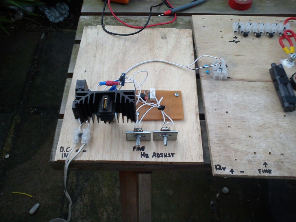


    But then things got even more strange. I couldn't get any sparks across the gap unless I held a grounded earth wire CLOSE TO the variable resistors, or unless I had my insulated pliers touching the variable resistors (I wasn't going to tune them with bare hands again!).
    This is all very strange. But if I touched the earth wire onto the 47k variable resistor it sparked inside (& smoked), if I touched it onto the 4.7k it made the sparks at the gap stronger.

    I had 2 grounded earth wires at this time, one was connected to the cold end of the coil.

    All very strange

    I'm guessing it's feeding back somewhere, maybe there's something wrong with my variable oscillator???

    Here's my HV coil......
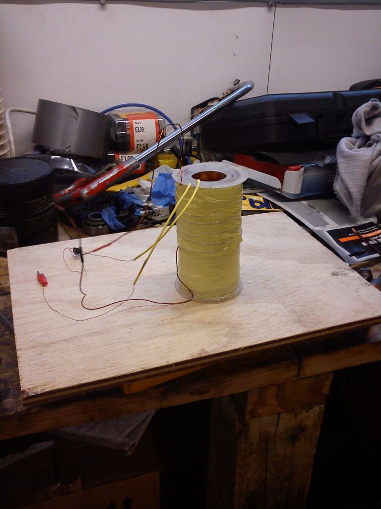


    Should I have both HV wires coming out the same end???

    I have a 2N3055 transistor, maybe I will just make up a fixed oscillator circuit with the base wired to a 4 turn coil, as per Patrick's other schematic???

    Comment


    • Originally posted by nutgone View Post
      I think they were still "live" even with the earth ground in place (the pic is not how I had it running, I had the coil on the right (reverse Tesla) disconnected, as it was just losing the sparks (obviously as it's not been tuned yet).

      I separated the LV side of things to a different board, like so......


      But then things got even more strange. I couldn't get any sparks across the gap unless I held a grounded earth wire CLOSE TO the variable resistors, or unless I had my insulated pliers touching the variable resistors (I wasn't going to tune them with bare hands again!).
      This is all very strange. But if I touched the earth wire onto the 47k variable resistor it sparked inside (& smoked), if I touched it onto the 4.7k it made the sparks at the gap stronger.

      I had 2 grounded earth wires at this time, one was connected to the cold end of the coil.

      All very strange

      I'm guessing it's feeding back somewhere, maybe there's something wrong with my variable oscillator???

      Here's my HV coil......


      Should I have both HV wires coming out the same end???

      I have a 2N3055 transistor, maybe I will just make up a fixed oscillator circuit with the base wired to a 4 turn coil, as per Patrick's other schematic???
      SEE PIC BELOW

      Attached Files

      Comment


      • Proper ground

        Shocks are the result of improper grounding. Earth is a large electron source or sink. You don't want to mess with Mother Nature... Make sure that anything you plan to touch is within a few volts of earth ground and limit the current that can flow through you to earth ground by appropriate use of resistors.
        There is a reason why science has been successful and technology is widespread. Don't be afraid to do the math and apply the laws of physics.

        Comment


        • Originally posted by drodenbe View Post
          Zilano Hi!

          I am trying to keep an open mind here but I guess I need some questions answered. I must be missing the boat here. I am a retired controls Eng. and an old ham radio operator and transmitter builder. Started with ham radio at twelve. Built my first 2 meter transmitter at 12 years of age. So I am not clueless.

          I retired 6 years ago and decided I needed to do something with my time. So one of the first projects I constructed was Don Smith's design. Even though everything in my education told me something was not right with his design and what he was saying I went and built it just like he explained and of course it did not work just like I thought it would not. So I put the coils in storage and worked on something else believing he was a crack pot and left it at that.

          So here I am again looking at these threads about Don in dis belief that no one has asked the questions I had. So in keeping with an open mind as always I am going to ask you!

          I am quite aware of how to get resonance from a tuned circuit with oscillator input. However not so sure what I need coming out of a spark gap or if it the same thing. This is what tesla designed and used in his transmitters which used a different type of wave propagation then what we use today. When the spark gap was dropped and the oscillator was introduced this changed the whole process and was used to hide and coverup the free energy aspect of his work. so saying all of that here is my questions.

          Coming out of a spark gap you have multiple frequencies developed. In Dons work he uses a 35kz high voltage device to feed the spark gap. Now he gave an example in his work on how to design the coils. But he used 24.7 mhz as his frequency not 35khz. He gave L1 as 10 turns and L2 as 26.66 turns. Is he saying that even though we are using 35khz to drive the spark gap he is going to use a harmonic produced from the gap at 24.7 mhz? If this is the case then I can see where maybe I went wrong. But there is no way you are going to drive a 10 turn coil with the capacitor value he used and have it resonate at 35khz. Also the fact that he said to divide 247/frequency for 1/4 wave. So if you use 35 khz that gives you 89,818 feet divided by 11 if you use a 3.5 inch form because you have aprox 11 inches per turn so that gives you 8,165 if I use #18 gage wire you get 22 turns per inch. So 22 *11 =242 inches per inch of coil length. Divide 8,165/242= 33.73 inch long coil.

          This not what don shows in his design. His coil should operate some where in the mhz range. So I guess if you can show me where I am wrong. It would be fantastic.
          Hi Drodenbe!
          sorry for replying u late.

          i did write u an elaborate reply but the forum thread had an error database error when i tried to post and it was lost as i did not save it. so it was not posted due to error.

          science is an adventure its not ventured by going by the book sometimes.

          spark is just interruptor to feed pulsed dc(made by spark) to primary. although all frequencies exists at spark gap no doubt. but treat it as a switch instead of a relay points.

          since L primary is of few turns it must be thick to produce some magnetic field.

          its easier if u go by rule 1/4 L-pri to 4L secondary(or L/2+L/2)
          to be more accurate weight of primary must be equal to secondary.

          yes 246 thing works and its the best way to use it.

          u can use any primary length and secondary is 4 times primary. dont Go with fixed frequency it can be changed using cap of appropriate mfd.

          u can have insights in my deleted posts saved as pdf and u may contact Mr. David fine for getting those pdfs
          i have covered elaborate details in those.

          learn more don documentation anywhere u lay hands on. its different from ham experience although same resonance works.

          always remember when we inject pulsed dc to parallel LC circuit it starts oscillating at its frequency determind by L and C.

          you need LCR meter.

          don thing is very entertaining and good for learning.

          the nst frequency has nothing to do with Lc frequency. u only have to maintain pri and sec. resonance.

          u have to learn more and it will take 3-6 months until u understand wots going on in don circuit so learn and use frequency wavelength calculators from net to ease urself and armed with right tools.

          keep following the thread u will learn more!

          wish u good luck!

          rgds
          ....
          Last edited by zilano; 05-26-2012, 10:50 PM.

          Comment


          • 555

            Also, I use the 555 quite a bit and in my circuit I send a pulse to the MOSFET gate so I can control the rep rate and the pulse width (down to zero) I use a small speaker to "listen" to my pulse rate. I design my coils to resonate at audio frequencies and find the actual real-life resonant frequency by observation. Don't abandon the 555 too quickly.
            There is a reason why science has been successful and technology is widespread. Don't be afraid to do the math and apply the laws of physics.

            Comment


            • Driving a MOSFET with a 555

              BTW, I use a small signal transistor to invert the polarity of the output (pin3) of the 555. That seemed the easiest and best way to do it.
              There is a reason why science has been successful and technology is widespread. Don't be afraid to do the math and apply the laws of physics.

              Comment


              • And Sweden is the winner
                This post is just as stupid as your former posts.

                Please use lager letters because your capitals begin to smell,

                Comment


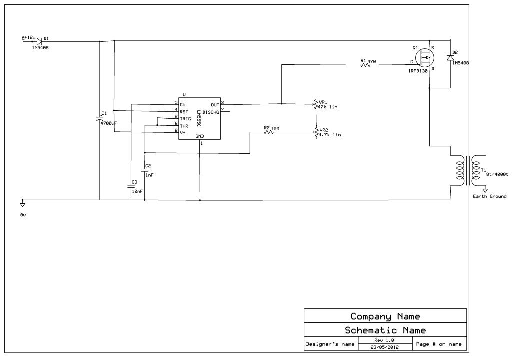
                • Right, here's the schematic of my variable oscillator (EDIT: I haven't wired in C1 or D1, as I'm working with a 12v battery at the moment)......


                  and here's the pic of the setup (again).....


                  Now, can anyone tell me why I should get a shock from the body of the 47k variable resistor (vR1)?

                  The cold end of the HV module was earthed.

                  Now, after that I moved the oscillator circuit to a separate board, like so (note, this pic was taken whilst clearing up, so the HV module is safely tucked away for the night).......


                  Now, with this setup I failed to get any sparks, UNLESS I held one of my earth wires CLOSE TO the body of either variable resistor.

                  I tried earthing the body of the 47k variable resistor, but it sparked inside & started to smoke!

                  Now, please note, while all this was going on, I got very similar results with the cold end of the HV coil earthed as with the earth removed. (I tried all different ways, with both earth grounds, which are separated by around 5-6 metres)

                  So, why is my 12v variable resistor body (which is isolated from EVERYTHING ELSE) live???!!

                  I tested the bodies of both variable resistors, & the spindles, with my multimeter, they are electrically isolated from EVERYTHING. It just doesn't make any sense.
                  Last edited by nutgone; 05-26-2012, 11:42 PM.

                  Comment


                  • Better frequency

                    Originally posted by drodenbe View Post
                    Xee2

                    so are you saying that I can choose any frequency I want and just adjust the spark gap for max output? Is there any one frequency better than another. What frequency did Kapanadze use? Thanks
                    I will come out bluntly and answer from my point of view. YES, you can pick any frequency, though your choice will have consequences. According to Don Smith's own words, in one of the videos of him, HIGHER frequencies are better. Watching and listening to his own words was very instructive for me. Too high and you have a lot of RF emission which you might want to avoid. But you well know the old AM was under 1 MHz. So, if DS used 24 MHz or 34 MHz or 45 or 47, it would sound reasonable to me. Second, the main coil that everyone focuses on is an air core. This would indicate higher frequency, rather than lower. I don't know what frequency Kap uses. I don't think it is important. The question you might want to consider is what frequency is characteristic of a spark gap? It seems that when the spark gap is conducting, sparking, etc. a very high frequency or group of frequencies is involved. What frequency is that? Well, it seems to be dependent on the circuitry in the local environment. Does it consist of any tuned components?

                    In my opinion, there are plenty of hard science questions that can be researched, because I can't seem to locate relevant data on the Internet. Given time and money, I will do some of that research and post my results.
                    There is a reason why science has been successful and technology is widespread. Don't be afraid to do the math and apply the laws of physics.

                    Comment


                    • Originally posted by nutgone View Post
                      Right, here's the schematic of my variable oscillator (EDIT: I haven't wired in C1 or D1, as I'm working with a 12v battery at the moment)......


                      and here's the pic of the setup (again).....


                      Now, can anyone tell me why I should get a shock from the body of the 47k variable resistor (vR1)?

                      The cold end of the HV module was earthed.

                      Now, after that I moved the oscillator circuit to a separate board, like so (note, this pic was taken whilst clearing up, so the HV module is safely tucked away for the night).......


                      Now, with this setup I failed to get any sparks, UNLESS I held one of my earth wires CLOSE TO the body of either variable resistor.

                      I tried earthing the body of the 47k variable resistor, but it sparked inside & started to smoke!

                      Now, please note, while all this was going on, I got very similar results with the cold end of the HV coil earthed as with the earth removed. (I tried all different ways, with both earth grounds, which are separated by around 5-6 metres)

                      So, why is my 12v variable resistor body (which is isolated from EVERYTHING ELSE) live???!!

                      I tested the bodies of both variable resistors, & the spindles, with my multimeter, they are electrically isolated from EVERYTHING. It just doesn't make any sense.

                      u r having kapanadze effect! ;-)
                      (pun intended)


                      plz do check ur 555 timer circuit. use all needed components dont drop caps from the circuit.caps also bypass ac frequencies while connected at dc polarity.


                      and do check ur primary coil with secondary they may be shorted with each other if not fully then partially. disconnect ur coil and use a dc tester the one that comes with an led and check that are they shorted or not. and remember to use insulation between primary and secondary coz high voltage can burn the insulation of the wire sometimes. and some times a nick or cut can cause this problem while winding coil. always wind ur coils carefully.

                      also check that u dont have any nick or cuts while working in ur hands or fingers as even small residual static will give u much more shock as compared covered skin.

                      rgds
                      ....
                      Last edited by zilano; 05-27-2012, 12:54 AM.

                      Comment


                      • The reason seems clear to me from reading your circuit diagram. You are switching the high side of the transformer. When the MOSFET switches OFF the BEMF drives the 555, caps, pots, etc. positive. The whole circuit is positive relative to earth ground. Hopefully, that is clear. In my equivalent circuit, the MOSFET is connected between earth ground and the BOTTOM of the coil. That way, the flyback transient appears between the top of the coil and the + of the supply and the + of the capacitor, etc. (C1 in your schematic) That is what it looks like to me.

                        'hope that helps.

                        Originally posted by nutgone View Post

                        Now, can anyone tell me why I should get a shock from the body of the 47k variable resistor (vR1)?
                        There is a reason why science has been successful and technology is widespread. Don't be afraid to do the math and apply the laws of physics.

                        Comment


                        • Ebook

                          Hi Patrick

                          Thanks for posting that circuit it is very exiting and gives me a starting point,
                          As I were following this thread I could not decide on what to start on, there were so many circuits floating around it became confusing. I believe that it should be a circuit that must be experiment on without confusing statements from distracters; it is funny that hardly anybody had any thing to say about it.

                          Thanks again
                          Best Regards
                          Johan

                          Comment


                          • Zappy stuff .

                            Originally posted by nutgone View Post
                            Right, here's the schematic of my variable oscillator (EDIT: I haven't wired in C1 or D1, as I'm working with a 12v battery at the moment)......


                            and here's the pic of the setup (again).....


                            Now, can anyone tell me why I should get a shock from the body of the 47k variable resistor (vR1)?

                            The cold end of the HV module was earthed.

                            Now, after that I moved the oscillator circuit to a separate board, like so (note, this pic was taken whilst clearing up, so the HV module is safely tucked away for the night).......


                            Now, with this setup I failed to get any sparks, UNLESS I held one of my earth wires CLOSE TO the body of either variable resistor.

                            I tried earthing the body of the 47k variable resistor, but it sparked inside & started to smoke!

                            Now, please note, while all this was going on, I got very similar results with the cold end of the HV coil earthed as with the earth removed. (I tried all different ways, with both earth grounds, which are separated by around 5-6 metres)

                            So, why is my 12v variable resistor body (which is isolated from EVERYTHING ELSE) live???!!

                            I tested the bodies of both variable resistors, & the spindles, with my multimeter, they are electrically isolated from EVERYTHING. It just doesn't make any sense.


                            Hi , Nutgone , Jacqui here ,
                            I see that you are having some resistive leakage and if I'm correct , it's no wonder . please tell me are the metal connectors that are on your board ; are they insulated at the board ?
                            That also includes that spark-gap , and if there not then I would say that's your problem .

                            Hi voltage like you are using needs adequate insulation and unsealed wooden boards are a quick way to go cross-eyed , real quick . There would be moisture in that board and that will turn it into a nice high resistance resistor , at 4Kv that's moving towards dangerous , as you've found out . The best advice I would give is to use 3mm acrylic sheet under low temperature fittings and sections of smooth ceramic floor tile under high temperature fittings . It's always good shop practice to use good quality terminal blocks , specially when hi-voltage is used .

                            Hope that is helpful , regards Jacqui .
                            Last edited by Jacqui; 05-27-2012, 07:58 AM. Reason: after thought .

                            Comment


                            • Hey People

                              I am posting a new schematic on the Don Smith based device I have built and I have made some changes

                              that a lot of you will not understand. I have taken out the capacitor after the step up because it was just

                              slowing down the ciruit and would not function right. I can't tell you why this is so. I just know what

                              is working for my system. I currently have diodes after the NST but I', not sure yet if they are helping or hurting.

                              But when I took out the caps my device just sprang to life. I had tried the caps in series and parallel with just problems.

                              And it is in resonance. No doughts Also I will post a picture of the lamp litt and me touching the ground to the other side of the plug prong

                              So here it is without caps and it is in resonance. So take or leave it this is what I have come up with and it works

                              This is a working Don Smith based device. mine just puts out AC and could easliy put out DC like Don's

                              So all this crap about how Don's devices don't work is B.S.. You just have to make some adjustments.

                              Like he always aid He was not giving all the information for a working Device. You have to work for it.

                              All aspects of this device works including the self charging battery, I need to run some more tests on it but its charging around 12v.

                              The charger with working schem and diodes and resitors is posted. And it has changed sence my last post so make note.

                              I have no doubts that this can be replicated buildt just like this and you can use feet instead of inches in the coil wire length.

                              Sense I used minni coils for my transformers.Which are just as powerful as pvc tubing coils. Best of Luck.


                              Regards
                              S-N-E

                              Attached Files
                              Last edited by SLOW-N-EASY; 05-28-2012, 04:51 AM.

                              Comment


                              • Originally posted by Jacqui View Post
                                Hi , Nutgone , Jacqui here ,
                                I see that you are having some resistive leakage
                                Hi Jacqui & thanks for that.
                                That's the first thing that crossed my mind when it happened, & I think it could be part of the reason, as the bodies of the VRs are only in contact with the wooden board, but it doesn't quite explain the other problems I was having with the spark gap only working when I bought the earth wire into close proximity with the VRs.

                                I do intend to use acrylic, or some other board which is a better insulator (or just better insulated terminal blocks).

                                Originally posted by wayne.ct View Post
                                The reason seems clear to me from reading your circuit diagram. You are switching the high side of the transformer. When the MOSFET switches OFF the BEMF drives the 555, caps, pots, etc. positive. The whole circuit is positive relative to earth ground. Hopefully, that is clear. In my equivalent circuit, the MOSFET is connected between earth ground and the BOTTOM of the coil. That way, the flyback transient appears between the top of the coil and the + of the supply and the + of the capacitor, etc. (C1 in your schematic) That is what it looks like to me.

                                'hope that helps.
                                Do you have a schematic of your circuit?

                                Originally posted by zilano View Post
                                u r having kapanadze effect! ;-)
                                (pun intended)

                                ......................and do check ur primary coil with secondary they may be shorted with each other if not fully then partially. disconnect ur coil and use a dc tester the one that comes with an led and check that are they shorted or not. and remember to use insulation between primary and secondary coz high voltage can burn the insulation of the wire sometimes. and some times a nick or cut can cause this problem while winding coil. always wind ur coils carefully.

                                ....
                                Thanks again Zilano. The coil was freshly wound yesterday & tests fine with a tester.

                                Could it be that the 8 turn primary is wrapped around the outside of the 4000 turn secondary???
                                I've also got 5 ferrite rods in the middle, maybe they're helping, maybe they're not???

                                Anyway, I will have another little play today, at some point. I've got other stuff to get on with as well (life goes on).

                                BTW, I used proper winding tape over my coils (the light yellow stuff you see in the pics), there is a layer of this in between the primary & secondary windings as well, so they should be insulated against each other.
                                I bought the tape specially, as I didn't want to use PVC insulation tape. Also this is higher temperature than normal tape, but I stayed away from the fibreglass tape, as I'm told that can have a bad effect on certain transformers.

                                This device is just a toy right now, as there are no capacitors involved in the HV side, & nothing is tuned to resonance. I was reading around 6v from my output coil at one point, but the most I connected to it was a multimeter.

                                Comment

                                Working...
                                X