If this is your first visit, be sure to
check out the FAQ by clicking the
link above. You may have to register
before you can post: click the register link above to proceed. To start viewing messages,
select the forum that you want to visit from the selection below.
use voltage divider between ht and primary input so u r saved from rewnding coil again. U WILL HAVE RIGHT INPUT VOLTAGE TO PRIMARY AND WHEN RESONANCE HAPPENS U WILL GET RIGHT VOLTAGE IN SECONDARY AS U WANT.
usa a variable resistor between battery and your flyback so u dont have to use the voltage divider and u can control voltage at source so your flyback will have required voltage for your primary.
So you mean that the fly-backs outgoing voltage be less then now let say 1200V and then there will be on each turn 240V meaning that the secondaries output will be about 6240V
1200V is enough for the HV module output.
Well I cant think any more, see You!
yes, Don achieved the same thing with variac when he was using ac driven Nst. here u r using dc driven flyback so u have to use a suitable variable resistor to control the input fed to ur flyback. less input to flyback less output voltage at flyback and so on.
I am looking for replicators who can assemble E. Leedskalnin flywheel and PMH in a way he did. Please let me know if anyone is willing to do hard work
I think I finally did put puzzle pieces together on E. Leedskalnin generator and we had proof of his fuelless generator almost for 70 years..
So instructions to remake one should be as following:
1) The flywheel is made from same pole magnets what are squizzed together by force to make sharp magnetic poles. Because of that we do not have strong magnetic field in then edges on the magnets. The strongest point is only in place where two same poles are did put together. With resonant spinning they make maximum electricity in PMH and cause no drag. Bye bye Lenz law if I am correct...
2) The 3 poles are fit in depth of PMH.
3) The PMH is inside of metal core (the box in photo). That amplifies magnetic currents (in E. Leedskalnin book).
4) The spark gap is used to take power out of high voltage from PMH on peaks only when magnets are approached already. NO MORE OTHER CONNECTIONS what are killing free oscillation!
the only free energy Leedskalnin machine is PMH itself. used with diodes to charge cap. it doesnt even need to use any mechanical power or priming electrical power to generate power. its based on earths magnetic field. we call it TPU.
Thanks for your help! however my uploads failed. Pull up the link FreeEnergyInventions.com and you will find all the info for photas, materials, background, operating description, etc. Note: the neon power supply used is no longer availabe because all the power supply companies changed their units internally to GFCI scenario so now they are useless for use with any free energy devices since they see any earth ground or spark gap in a circuit as a fault and auto trip!!!!! (@#$%&*() nice words really. I noticed a china supply unit mentioned to XILO earlier that could be used instead maybe. try the info and enjoy! mike.
Thanks for bringing this up.
I am thinking about getting a NST.Still concerned about the GFCI, to counter that I am thinking that if we just pulse one side of a capacitor with the positive leads, would the GFCI still trip? The neutral would have been left ungrounded.
Any possibility of this working?
I have found my flyback to very reliable.I have actually been collecting em from tv repair shops along with capacitors and assorted stuff.I try to have them in various sizes.The unfortunate thing is that I am not certain of the voltages.They are definately over 2000 volts based on the length of the arcs in the sparkgap.Fortunately,I took a chance and got manageable voltages from the other side of a homemade capacitor.
LtSpice is definately worth trying out.The evidence is not concrete,but trying plauson,albiet with no spark gap and various combinations of capacitors and modified circuit designs from are showing some striking results.I do feel nervous about the outputs I see sometimes showing up when i tweak values.
There is so much to learn.
I would like for Zilano and T-1000 to finish their last dialog.I found it quite interesting...
when u upload the pic on this forum it shows as thumbnail in the post u posted. now go to ur own post and just right click on the thumb image of ur own post and select open in new window. another window will open and will show u the larger image of the pic u saw in thumbnail. again right click that big image and select copy and come to ur own post page and click edit it will open the edit window to edit ur post. now where ever u want to paste the picture in ur own posted text just right click and select paste and ur image gets pasted along with ur posted text.
its called inline embedding pictures. same way u can paste any image along with text. the same feature apply in emails too.
rgds
zzzz
Thanks! I've always wanted to do this but never got to it.
Thanks. That is excellent building guide. Was Don Smith the author?
No- smith was not the author. the author was a member of freeenergyinventions.co. however don smith was the designer of this exact build as it was one of his earlier devices as shown in my attachments. notice the exact similarities as you will see. thanks for reading, mike.
Don Smith uses 8000V capacitor on the L2 side, and if the NST output is 2000V then L1 with 5 turns will have 400V on every turn, and as the L2 has 2*17 turns or 34 turns then the outgoing voltage would be
Did he take only one side of the coil for voltage and the other side gives the amperage
which one to follow?!
rgds blackrobi
don coils work like 12-0-12 transformer if u leave the middle end and take output from extreme ends the voltage will be 12+12=24 volt
if u join extreme ends and take output from joined extreme ends and middle tap then the voltage is 12 volts.
the 17 +17 turns joined and middle tap will give you 6800V
else if u take output from extreme ends leaving middle tap then ur output voltage will be 13600V
u have to do hit and trial method. use a variable resisitor able to handle atleast 5 amps and connect in series with battery and the oscillator circuit of ur flyback keep it lowest and try to run ur circuit. and slowely increase it so u get optimum voltage on secondary that u want.
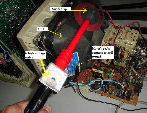
if u could measure the hv of ur flyback voltage with a hv probe if u have one then its easy. else u have to do hit n trial method using variable Resistor in series with ur battery.
Thanks for your help! however my uploads failed. Pull up the link FreeEnergyInventions.com and you will find all the info for photas, materials, background, operating description, etc. Note: the neon power supply used is no longer availabe because all the power supply companies changed their units internally to GFCI scenario so now they are useless for use with any free energy devices since they see any earth ground or spark gap in a circuit as a fault and auto trip!!!!! (@#$%&*() nice words really. I noticed a china supply unit mentioned to XILO earlier that could be used instead maybe. try the info and enjoy! mike.
Hi Mike!
plz post the link in reply. copy the link of website and paste it in your reply. so all members can see the page u r refering to.
Hi Mike!
plz post the link in reply. copy the link of website and paste it in your reply. so all members can see the page u r refering to.
thank you for ur effort and zeal!
thankx for the info and welcome to the forum!
regards
zelina
Hello Zelina-the page I was referring to was at freeenergyinventions back in october of 2010-since then when I pull up the site I find it has been sold and dont have the former sucess with the page- however I did save it to my computer back then and I did just post the pieces of info as you can see above in the recent posts. thanks for you reading and interest, mike.
Comment