Announcement

Collapse
No announcement yet.

Donald Smith Devices too good to be true

Collapse
X
 
  • Filter
  • Time
  • Show
Clear All
new posts

  • Originally posted by drak View Post
    Ok, I was able to tune my custom nst from a range of 170khz to a little below 17khz using a cap bank array and a bunch of switches. I got tired of swapping caps on a breadboard. Yeah I know there is probably better ways to do it but it got the job done for me.


    Using Don's silent spark gap configuration I went slowly from 170khz down to 17khz on my nst while my coils were set to resonate at 224khz. I got nothing.

    I changed my coil set resonance down to 148khz and scanned again, nothing.
    Maybe Don did purposely change the schematics. Although he did say when the device was running the lightning arrestor just glowed.

    By nothing I mean I think a fly landed on my L2 coil while I was testing and it just sat there and stared at me.

    Any suggestions?

    Hi drak!

    your circuit and don circuit is right. Do you have rf frequency meters?

    don circuit is Rf based and you only can see output not before diodes.

    its not tesla circuit.

    your scope measures electrical frequency not radio frequency.

    i made joule thief and wrongly connected coils not as cw and ccw but cw cw and i could not light the led. i spent 3 days then i remember making short wave transmitter circuit it had same coils cw cw in the oscillatory coil. it needed the radio to see if circuit worked or not. so i tried a radio near the joule thief wound cw cw and when i tuned in i heard sound hissing sound in radio and when i turned off joule thief the sound went away.
    then i did one thing i made similar turns single coil on similar ferrite ring and added diode across the two ends and it lit and range was from 6 inches to 50 meters.

    later i wound Jt coils as cw and ccw and led lit due to electrical frequency not by radio frequency.


    full regards

    XILO
    (zero voltage input)
    Last edited by xilo; 06-16-2012, 06:16 AM.

    Comment


    • Originally posted by xilo View Post
      Hi drak!

      your circuit and don circuit is right. Do you have rf frequency meters?

      don circuit is Rf based and you only can see output not before diodes.

      its not tesla circuit.

      your scope measures electrical frequency not radio frequency.

      full regards

      XILO
      (zero voltage input)
      No, I do not have an rf frequency meter.

      I have no clue what you just said. I was measuring it by led's, light bulbs, an o-scope, and house flies, after the diodes and before.

      Comment


      • Originally posted by drak View Post
        No, I do not have an rf frequency meter.

        I have no clue what you just said. I was measuring it by led's, light bulbs, an o-scope, and house flies, after the diodes and before.
        Hi drak!

        did you use ferrite core? if not then insert any ferrite core and check output at diodes after secondary. if you dont find output then short one of the two diodes after secondary with a conducting wire then check output with bulb.

        but before you do every thing mentioned above its necessary that secondary is in tune with primary. so slide primary within secondary or slide the ferrite core.

        use ferrite else nothing u will see in output.

        full regards

        XILO
        Attached Files
        Last edited by xilo; 06-16-2012, 06:59 AM.

        Comment


        • Originally posted by xilo View Post
          Hi drak!

          did you use ferrite core? if not then insert any ferrite core and check output at diodes after secondary. if you dont find output then short one of the two diodes after secondary with a conducting wire then check output with bulb.

          use ferrite else nothing u will see in output.

          full regards

          XILO
          tomorrow, try I will, give me time you must.
          Last edited by drak; 06-16-2012, 06:40 AM.

          Comment


          • Originally posted by drak View Post
            tomorrow, try I will, give me time you must.
            Hi drak!

            in earlier model as table top don used radio resonance. in later models he used tesla electrical resonance. the pic below will clear your doubt.

            the + sign you see in the picture is the diode end and - is cold end. the combination don used is same to the spark gap transmitter circuit. see below

            ps: spark is always at cold end of nst/flyback


            since radio frequency cannot be directly used to charge batteries so Don used the yellow coil to charge the battery using a dioded circuit with overcharge protection circuitry. In later models Tesla electrical resonance method was used and this lead to the way of wire length to charge the battery automatically and later that yellow coil was not used to charge battery and He changed table top circuit to tesla electrical resonance method and resonant wire length was used to charge batteries and yellow coil was never used but it remained on the model as just a show piece.

            Don found that tesla method is much more effective and efficient and Mr. clean used the same method and have success! but Mr. clean used kapanadze secret the caduceus coil where as Don used split opposite coils to suppress secondary coil effecting primary.

            where as when using radio resonance the primary and secondary are wound in same direction. the secondary in radio resonance is a split coil but have same direction else radio resonance wont happen.

            now you can decide which way to go what type of circuit to use. I feel mr. clean method is same as followed by Don smith so its much better option. use what don used for spark gap and sound will be low. using earth ground also supresses sound of spark gap.


            full regards

            XILO
            Attached Files
            Last edited by xilo; 06-16-2012, 08:16 AM.

            Comment


            • Originally posted by drak View Post
              Ok, I was able to tune my custom nst from a range of 170khz to a little below 17khz using a cap bank array and a bunch of switches. I got tired of swapping caps on a breadboard. Yeah I know there is probably better ways to do it but it got the job done for me.

              Using Don's silent spark gap configuration I went slowly from 170khz down to 17khz on my nst while my coils were set to resonate at 224khz. I got nothing.

              I changed my coil set resonance down to 148khz and scanned again, nothing.
              Maybe Don did purposely change the schematics. Although he did say when the device was running the lightning arrestor just glowed.

              Any suggestions?
              Hi Drak.
              You seem to have done a lot of good work. Congrats !
              Don`t give up, it is simple once one understands the principle behind Don`s devices.
              I know this will sound a bit overstressed , but take your time and read again what Don himself has to say about his circuits in his writings and videos.
              Now I am not sure for this but you probably should not use capacity at μF range because the more capacity the less the frequency.
              And a question here. Why you need to step down the frequency since most people are saying
              you get better results within a range 30Kcps to 35Kcps (KHz) ??
              Something to consider is to have your HV transformer input variated so it is easier to find resonance.

              Originally posted by drak View Post
              By nothing I mean I think a fly landed on my L2 coil while I was testing and it just sat there and stared at me.

              Hey do not be discouraged.
              I bet that fly better force itself elsewhere when the next time you will succeed !
              Regards.
              << BP Ultimate + Shell-V Power + Allies (opec) = the Ultimate Power Aligators to Suck People`s Blood !-! >>

              Comment


              • Originally posted by xilo View Post
                Hi drak!

                in earlier model as table top don used radio resonance. in later models he used tesla electrical resonance. the pic below will clear your doubt.

                the + sign you see in the picture is the diode end and - is cold end. the combination don used is same to the spark gap transmitter circuit. see below

                ps: spark is always at cold end of nst/flyback


                since radio frequency cannot be directly used to charge batteries so Don used the yellow coil to charge the battery using a dioded circuit with overcharge protection circuitry. In later models Tesla electrical resonance method was used and this lead to the way of wire length to charge the battery automatically and later that yellow coil was not used to charge battery and He changed table top circuit to tesla electrical resonance method and resonant wire length was used to charge batteries and yellow coil was never used but it remained on the model as just a show piece.

                Don found that tesla method is much more effective and efficient and Mr. clean used the same method and have success! but Mr. clean used kapanadze secret the caduceus coil where as Don used split opposite coils to suppress secondary coil effecting primary.

                where as when using radio resonance the primary and secondary are wound in same direction. the secondary in radio resonance is a split coil but have same direction else radio resonance wont happen.

                now you can decide which way to go what type of circuit to use. I feel mr. clean method is same as followed by Don smith so its much better option. use what don used for spark gap and sound will be low. using earth ground also supresses sound of spark gap.


                full regards

                XILO
                Hello all-clarence here- now to some important info----the below attachment is an exact! first build and shown in the hands of don smith himself! of the first Items #1 thru #7 (less capacitor but you can discern a spark gap control on the terminal strip if you look hard!) that you show on your schematic and by the way that is the schematic of the suitcase model he used at the 1966 symposium and not the L1 L2 slide tube device. happy regards and enjoy-onward! mike.
                Last edited by clarence; 07-23-2012, 05:05 PM.

                Comment


                • Originally posted by clarence View Post
                  Hello all-clarence here- now to some important info----the below attachment is an exact! first build and shown in the hands of don smith himself! of the first Items #1 thru #7 (less capacitor but you can discern a spark gap control on the terminal strip if you look hard!) that you show on your schematic and by the way that is the schematic of the suitcase model he used at the 1966 symposium and not the L1 L2 slide tube device. happy regards and enjoy-onward! mike.
                  Hello all-regarding my last post- after completion of the 1-7 items don is shown holding in his hands the rest of the build is just pure assembly work as you can see. hope you all enjoy and profit. thanks for your reading, mike.

                  Comment


                  • Originally posted by soundiceuk View Post
                    @ Xilo

                    Thanks for plugging the forum without any sort of prompt.


                    @ All

                    Sorry for my lack of communication.

                    Despite being able to enter your details on www. energy. team-talk. net

                    The forum is not freely accepting new members.

                    Bruce's 2nd Edition, which is nearing completion will feature schematic, videos and pictures of a multi-kilowatt device for purchasers to replicate. Anyone who has purchased a copy of the 1st Edition will be given a free upgrade.

                    If anyone would like to reserve a copy of the 2nd Edition. Firstly please contact me via pm.

                    Anyone who reserves a copy will receive a copy of the 1st Edition and given access to the forum within 24 hours.

                    This way, only the serious folks will be onboard.

                    As a bonus you will be receive Don Smith's Obtaining Energy from the Earth's Magnetic Flux 2 x DVD files & also Radiant Energy Collection CD-ROM files and help/support from our members to build your device.


                    @ Gedfire

                    My conclusion with Don's work is that it is not self sustaining. I'm not certain what happened to Dynatron but his videos looked the most promising for a break through. I would love to see a replication that is self sustaining.

                    I have 70% of the components to build Bruce's device. I intend to pursue his work, instead of Don's. I have a real soft spot for Don's work. We wouldn't be here without him!

                    @ GSM

                    The main reason I am doing what I am doing is because my research has shown me that we are all about to be heavily shafted by the greediest people on the planet

                    Have you watched Thrive?

                    Have you watched Thrive Exposed?


                    @ All

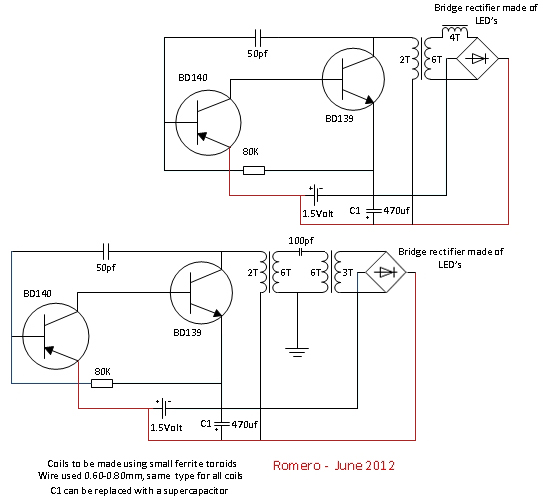
                    Here is a very interesting circuit for you to look at by one of the world's greatest electronics wizards!!!

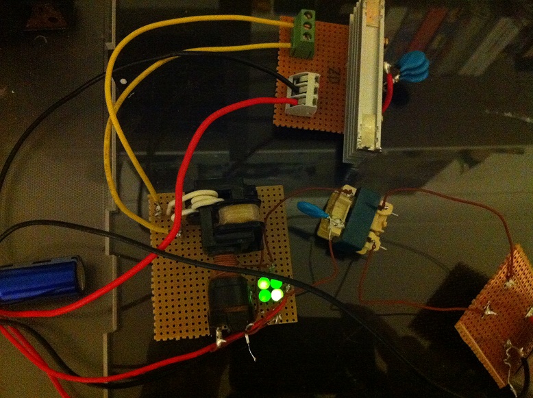
                    It has been running for over 3 weeks now without the battery, after initial capacitor charging.


                    CAn you post the link of the thread where Romero posted that pictures?
                    I tried to find them on his forum Free Energy but no succes...

                    thanx

                    Comment


                    • Nice setup

                      Nice setup there Drak. Try to adjust SG for frequency change.
                      Slow n Easy that last schematic with parallel diodes is better than in series? cause I'm having trouble with my diodes to charge the bank.
                      Thanks

                      Comment


                      • Here tis -

                        Schematic self run system.

                        Comment


                        • Xilo is correct. Btw Don Smith on that picture above is keeping transformer when secondary does not affect primary. They exists and in various models.
                          Even Tesla had patent of one not much effective when phase relationship of voltage and current is shifted in secondary so the resulting Lenz effect on primary is partially adding energy to the primary flux. It has the ability to lower power consumption of primary when heavy loaded secondary to some point.
                          The other class of models are also described by Don Smith and is using magnetostriction to generate precisely power in spikes synchronized with resonant frequencies of input and output so when Mr Lenz is trying to mess up it finds an open circuit or something like that. Or by using long ferromagnetic rod with series inductances - transformers - using the so called lag in propagation of magnetic field flux in ferromagnetics as a delay for eliminating Lenz law effects.
                          Why we are here discussing Don Smith instead using any of such class devices today ? Because we still don't know what electricity is !

                          Comment


                          • Hey, slow-n-easy

                            Originally posted by drak View Post
                            @SLOW-N-EASY


                            An input of 9500 volts into a voltage divider using an 80ohm and a 1ohm resistor yields 117.284v. What kind of inverter is that? Where can I get one that is tested by the manufacturer?

                            Maybe its supposed to be 800ohm? That would make the output 11.86v.

                            I have the same question, is it a 110-110 inverter or 12-110(or 240) inverter.
                            12v-mains inverters are commonly available things.

                            My understanding of voltage dividers is the more current you draw from the mid-point the more of a voltage drop you get so maybe the 117v is whats needed to provide 12v output when the inverter is under load?

                            Also what type/size cap are you using slow-n-easy? Can electrolytics be used here seeing as you have your cap on the output of the rectifier?


                            400px-Tesla_coil_bipolar_807x975.jpg

                            Comment


                            • romerouk.principle

                              romerouk.principle

                              electrical power generation

                              free energy using earth ground. kilowatts of power can be generated using spark gdt tubes using tesla electroststic resonance. earth ground is very important to have free energy or an antenna for those who dont want to use earth ground.


                              best regards

                              dunfasto
                              Last edited by dunfasto; 08-24-2013, 10:58 PM.

                              Comment


                              • @ Drak

                                I thought these might help

                                http://www.youtube.com/v/I1t4hLBJQnY

                                http://www.youtube.com/v/qD2DOGF46I4

                                http://www.youtube.com/v/FOPLa_9uazk

                                Dynatron is using spark gap made of tungsten electrodes 6 mm in diameter. Tungsten is inserted into brass bolts.

                                Tungsten is pure without additives.

                                A vacuum spark gap works much better.

                                Last edited by soundiceuk; 06-16-2012, 02:21 PM. Reason: addition

                                Comment

                                Working...
                                X