Announcement

Collapse
No announcement yet.

Donald Smith Devices too good to be true

Collapse
X
 
  • Filter
  • Time
  • Show
Clear All
new posts

  • need for high voltage probe to measure oscillator output and receiver coil output

    hello and regards to all. awhile back on the thread someone mentioned fine words concerning their KAISE-SK9000 high voltage probe. I could sure use the information to know where to buy such a device and its approximate cost. my build is the center transmitter and receiver only as shown in the attachment of the don smith device my build is complete except for bringing the L1 device into resonance with my oscillator input @ 42.5KHZ. my L1 and L2 coils are 1/4 wave setup ( L1 is #8 barker and williams 4" dia @ 6.6 turns which is 84 inches length and L2 is #12 barker and williams 2 1/2" dia @ 42.8 turns which is 336 inches). when L1 is tuned to resonance with oscillator @ 42.5 KHZ then it will automaticly talk to the L2 coil as transmitter-receiver 1/4 wave relationship. my L1 coil has 7.9uH L and corresponding 1770pF gives the resonant frequency of 42.5 KHZ. my capacitors for the pF value @ 2000v rating should be in shortly from digikey and I will finish the assembly and evaluate the results (device design of my build is 377v oscillator input which puts 57.12v on each turn of L2 giving output of 2444.7vac @ 20 amps. the resultant output equals 48KW to a load transformer of 50 kva. again to effect this end I need an effective high voltage probe. all information and comments welcomed by all. onward!
    Last edited by clarence; 07-23-2012, 05:05 PM.

    Comment


    • Originally posted by clarence View Post
      hello and regards to all. awhile back on the thread someone mentioned fine words concerning their KAISE-SK9000 high voltage probe. I could sure use the information to know where to buy such a device and its approximate cost. my build is the center transmitter and receiver only as shown in the attachment of the don smith device my build is complete except for bringing the L1 device into resonance with my oscillator input @ 42.5KHZ. my L1 and L2 coils are 1/4 wave setup ( L1 is #8 barker and williams 4" dia @ 6.6 turns which is 84 inches length and L2 is #12 barker and williams 2 1/2" dia @ 42.8 turns which is 336 inches). when L1 is tuned to resonance with oscillator @ 42.5 KHZ then it will automaticly talk to the L2 coil as transmitter-receiver 1/4 wave relationship. my L1 coil has 7.9uH L and corresponding 1770pF gives the resonant frequency of 42.5 KHZ. my capacitors for the pF value @ 2000v rating should be in shortly from digikey and I will finish the assembly and evaluate the results (device design of my build is 377v oscillator input which puts 57.12v on each turn of L2 giving output of 2444.7vac @ 20 amps. the resultant output equals 48KW to a load transformer of 50 kva. again to effect this end I need an effective high voltage probe. all information and comments welcomed by all. onward!
      Very exciting man, cant wait to see what you put together!
      Here is what i would call proof of concept for the pic you attached


      smit1 - YouTube
      In the beginner's mind, there are many possibilities.
      In the expert's mind there are few.
      -Shunryu Suzuki

      Comment


      • Originally posted by olo View Post
        Hi all

        hi olo

        just an update of this video

        hope this helps

        good luck at all

        Laurent

        charging by induction directly connecting to motor - YouTube

        Comment


        • Originally posted by necromanser View Post
          Hi Vasiliy,
          Thank you for the translation. This will give me something to get going. I believe the radiant is being drawn from the coil arrangement on the flyback and resonant frequency. But thats just me. Thank you much once again.

          Regards,
          HS
          Hi, necromanser & all
          By the way, I forgot to add. In the video, saying that the output voltage of high voltage transformer, about 2 ... 3 kV.
          Perhaps the primary winding rewound, otherwise the output voltage was-would be more.

          Best Regards

          Comment


          • Originally posted by woopy View Post
            Hi all

            hi olo

            just an update of this video

            hope this helps

            good luck at all

            Laurent

            charging by induction directly connecting to motor - YouTube
            Hi woopy

            thanks for the update video. the fast running motor makes me whirrrr too.

            unlimited possibilities i see watching your video.

            thank you so much for very amazing videos.

            olo

            Comment


            • Originally posted by mr.clean View Post
              Very exciting man, cant wait to see what you put together!
              Here is what i would call proof of concept for the pic you attached


              smit1 - YouTube
              thanks Mr.Clean, I loved the proof of concept tremendously. BTW I made a typo error on the value of the caps I stated, instead of 1770pF it should have been 1770nF - sorry about that!

              Comment


              • Kacher tests

                Originally posted by woopy View Post
                Hi all

                hi olo

                just an update of this video

                hope this helps

                good luck at all

                Laurent

                charging by induction directly connecting to motor - YouTube
                Hi Woopy,

                Great work - well done !! I love all of your videos and especially your style of presentation. Not being a builder myself, I hesitate to make any comments, but here goes. I really would appreciate it if you would run a few very quick tests to clarify the situation a little further:

                1. Would you please remove the copper plate and see if that makes a difference. I suspect that the copper plate is not being used in this set-up, but there is only one way to check that.

                2. I think that the reason that the second Avremenko plug works best when connected to the battery negative is because the positive feed to the motor is through the forward-facing diode of the first Avremenko plug and coming at high voltage from the Kacher circuit. Connecting to the battery minus gives the motor 24V extra voltage. Would you please test this by disconnecting the second Avremenko diode going to the motor plus, and if that makes no difference, then using a direct connection between the battery minus and the motor minus as it is distinctly possible that the second Avremenko is not needed.

                3. It is not clear if the back-EMF of the motor is contributing to the operation of the circuit as it is at the moment, so if you happen to have one of those very cheap 12V 150W inverters, would you please try it, first, across the motor and then without the motor.

                4. I think that your present circuit is VERY important. To establish what components come into play in it's operation, would you please remove the wire spiral inside the Kacher coil to see if it is having an effect. I know that it does not have a physical connection in the circuit, but at these frequencies that doesn't mean much.

                If you are kind enough to try these tests and any components get damaged as a result, then I will be more than happy to pay for replacement parts.

                Impressive progress - well done !!

                Patrick

                Comment


                • Just my 2 cents
                  I am a builder, although on a small budget. My bench is littered with both good and bad circuits. I don't post much because I haven't discovered anything that is going to move us further forward. If I do I will post it right away. If it wasn't for the open forum with the combined work of the builders like Mr.Clean and Woopy (many others) together with the people like Patric Kelly who bring it all together I think the advancement would be very slow. I think we just need to ignore and maybe not even respond to the people who want to clog up the place.

                  Comment


                  • Originally posted by clarence View Post
                    my build is the center transmitter and receiver only as shown in the attachment of the don smith device my build is complete except for bringing the L1 device into resonance with my oscillator input @ 42.5KHZ.
                    At last someone picked up this circuit!

                    Did you use iron / nickel as coils?
                    This circuit was supposed to clone magnetic field in receiving coils by using those metals because they have magnetic field amplification property when they are close to magnet.

                    Cheers!

                    Comment


                    • MOcaps discharge rate

                      Showing my two MOcaps 2kv 1.05uf each discharge rate on Don circuit without coils as Bruce had said:

                      MOcaps discharge rate - YouTube

                      Thanks

                      Comment


                      • iron / nickel

                        Originally posted by T-1000 View Post
                        At last someone picked up this circuit!

                        Did you use iron / nickel as coils?
                        This circuit was supposed to clone magnetic field in receiving coils by using those metals because they have magnetic field amplification property when they are close to magnet.

                        Cheers!

                        Do you mean one coil iron and one coil nickel?

                        Or do you mean an iron nickel alloy? Like permalloy.

                        Permalloy wire/rod - Permalloy | Permalloy

                        Comment


                        • make dead go live!

                          Hi woopy

                          money saver!

                          make dead come alive !

                          save earth, save energy.

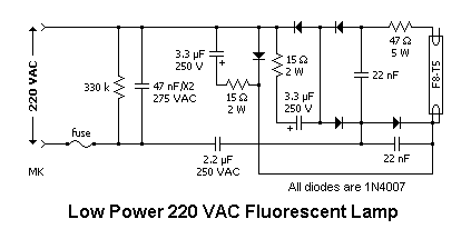
                          Burnt CFL Re-Light - YouTube

                          http://makelifeeasy.yolasite.com/


                          olo

                          Comment


                          • Dear Mr. Clean and Friends

                            Kurt, you know that I am working on a Don Smith device, and have been following your replication. I have also read all of this thread and am experimenting every day on my circuit. I don't post many videos, but that doesn't mean anything.

                            I am posting this today because I really want to see everyone here get a working device.

                            It has been alleged by a forum member, who has a very useful eBook on this topic, that another member of this forum has a working Don Smith device powering their home. What I can't understand is why that person doesn't post a video of it, and why that person doesn't give us the exact circuit they are using.

                            Everyone here is contributing their efforts toward a open-source device for the whole world to build and use. Why is it so difficult for the builder of this device to really back up his/her word to help the world by demonstrating his/her device for us to replicate?

                            If that person still refuses to help further, I would suggest that we try to build the device based on what we already know. Kurt, and all you others that want this, do you think it would be a good thing, since you have demonstrated your efforts, to give a summary of where you are and what is the current obstacle that you need to overcome? Then we all try to help you overcome that one thing. When you get to the next problem, we all rally and try to help overcome that one. The greatest consideration will be given to those members who are actually builders.

                            If we make this a real team effort, we will surely succeed!

                            I know there are folks on this thread who genuinely believe that we are wasting our time and have tried to warn us of this. Some of the things they have added should be taken as valuable information. Their advice, complaints, etc. to follow the scientific method is very important for us to comply with. If we would do that, they would not complain so much, and we would stay on the trail to success. There would be less time wasted in rabbit trails. LOL

                            If the people on this thread would start acting like a team instead of a bunch of individuals, we would surely succeed in getting a working device. Remember, everyone, there is no I in TEAM.

                            I know that I don't really have a "right" to say these things, but I sincerely desire that we succeed at building a device that can power our machines without the need for the grid!

                            Have a great day, Kurt and every builder on this thread!!
                            I believe in THE Way, THE Truth and THE Life.

                            Comment


                            • don smith build- recent post

                              Originally posted by T-1000 View Post
                              At last someone picked up this circuit!

                              Did you use iron / nickel as coils?
                              This circuit was supposed to clone magnetic field in receiving coils by using those metals because they have magnetic field amplification property when they are close to magnet.

                              Cheers!
                              Hello T-1000 and all, the coils I used were from barker and williams airdux lexan coils per the attached thumbnails. I choose these particular coils as they seemed to fit the eyeball dimensions of the coils in dons own build pic also attached. additionaly all of their coils except for mini's are ten inches tall and if you will note their shown uH value for full length of the coils is very close to a per/inch of coil height match which helps in a 1/4 wave transmitter-receiver relationship and makes resonance very very close. I belive its a very close almost match in coil wire weights between L-1 and L2 which is very beneficial. as I said in previous post L-1 has 6.6 turns (7 ft) to L-2 42.8 turns (28 ft) which is dons specified 1/4 wave recommendation. additionaly I have found that any oscillator power circuit should be a variable frequency circuit so that it can be itself tuned into reasonance first and then L-1 coil cap to inductance set to match that reasonance frequency. NOT all oscillator power supplys are actually at reasonance as might be supossed. reasonance is the key to tapping into the ambient environment energy that is waiting for us all! Tesla, Smith, Moray, etc. all determined this knowledge to themselves to achieve ther beautiful results. joy and sucess to all, onward!The part numbers I used were for L-1...3204TL 51uH and for L-2...2006TL 57uH.
                              Last edited by clarence; 07-23-2012, 05:05 PM.

                              Comment


                              • the coils used are the same coils don used in most of his builds

                                Originally posted by clarence View Post
                                Hello T-1000 and all, the coils I used were from barker and williams airdux lexan coils per the attached thumbnails. I choose these particular coils as they seemed to fit the eyeball dimensions of the coils in dons own build pic also attached. additionaly all of their coils except for mini's are ten inches tall and if you will note their shown uH value for full length of the coils is very close to a per/inch of coil height match which helps in a 1/4 wave transmitter-receiver relationship and makes resonance very very close. I belive its a very close almost match in coil wire weights between L-1 and L2 which is very beneficial. as I said in previous post L-1 has 6.6 turns (7 ft) to L-2 42.8 turns (28 ft) which is dons specified 1/4 wave recommendation. additionaly I have found that any oscillator power circuit should be a variable frequency circuit so that it can be itself tuned into reasonance first and then L-1 coil cap to inductance set to match that reasonance frequency. NOT all oscillator power supplys are actually at reasonance as might be supossed. reasonance is the key to tapping into the ambient environment energy that is waiting for us all! Tesla, Smith, Moray, etc. all determined this knowledge to themselves to achieve ther beautiful results. joy and sucess to all, onward!The part numbers I used were for L-1...3204TL 51uH and for L-2...2006TL 57uH.
                                Hello again T-1000 and all. In answerer to your question about the type of coils I used thry are the very same off the shelf coils that don smith used in the majority of his coil builds due to quality of product and availability. why try to make it when what has already been used works well. The L-1 coil is a bit expensive but when you consider that one of that particular coil can make three L-1's for duplicate backups of the same device. just an observation on my part. as always, enjoy and progress to a fruitful end. mike. onward!

                                Comment

                                Working...
                                X