 Tweet
Tweet
Janost
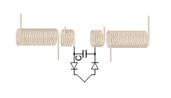
I'll give a quarter for the description on how this thing works... makes no sense to me.
Larry
I'll give a quarter for the description on how this thing works... makes no sense to me.
Larry
Originally posted by janost
View Post


Comment