If this is your first visit, be sure to
check out the FAQ by clicking the
link above. You may have to register
before you can post: click the register link above to proceed. To start viewing messages,
select the forum that you want to visit from the selection below.
They believe the project's finished and they gave enough information to make it self-running (no video with measurements though), and as I know they're up to new project, not connected to Smith.
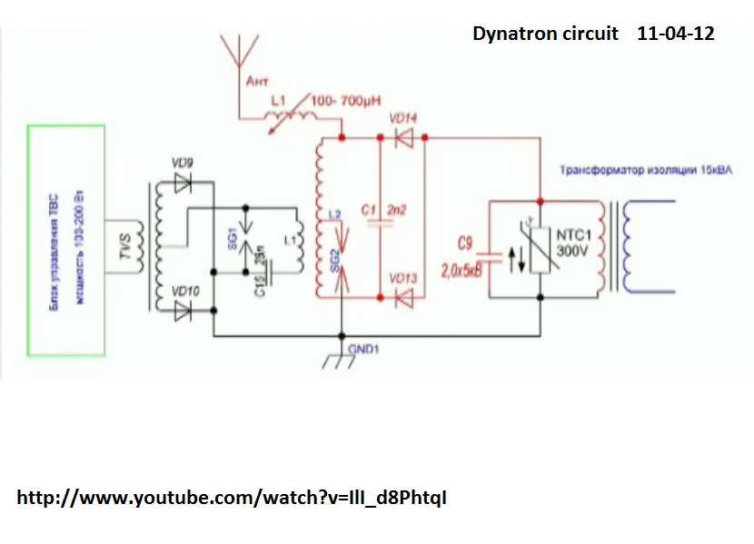
cool, actually that looked like the Smith with a toroid stack for step-down transformer. i dont speak the language tho
and the small details which are new are in line with the old transistor radio circuits....hehe and matter of fact im planning some really cool stuff with my spare B&W coils involving identical radio battery-LESS reciever circuits...
i have noticed he has multiple channels, anywy lets hope he never stops creating
In the beginner's mind, there are many possibilities.
In the expert's mind there are few.
-Shunryu Suzuki
cool, actually that looked like the Smith with a toroid stack for step-down transformer. i dont speak the language tho
and the small details which are new are in line with the old transistor radio circuits....hehe and matter of fact im planning some really cool stuff with my spare B&W coils involving identical radio battery-LESS reciever circuits...
i have noticed he has multiple channels, anywy lets hope he never stops creating
Unfortunately when SG involved it's not possible to make correct measurements with regular meters (at least for me), that's why he's trying to prove a hi-current output with wire heating (others doing it with lightbulbs).
And he's complaining - weak transformer, bad ground, bad antenna, diodes getting very hot, so the whole setup actually could be made better, but I like the idea of getting the antenna and ground in this way to get the potential of "outside" energy (and it's huge) to be involved.
Anyway, it still have HF output, which has to be transformed in input range, which's not shown yet, they just discussing how it's gonna be (other transformer, caps, inverter, etc).
So, it's not over yet.
hi everyone, got some new stuff about the Bitoroid....very... interesting.
hehe... golden egg?? i dont wanna speak too soon, but this looks like "it" ... the "it" we have been searching for. I think i did all i could to show input and output readings and the behaviour of the 3 circuits during operation.
The idea is to use this as a HV driver for my big Don Smith device board. one thing at a time, but that is the reason for combined designs
Input is 12v fixed @ .5amp
Output measured at 30v @ .47amp
2.93Khz resonant tuned
L1 29.5mH and 100nF
L2's 178mH and 17nF on each
Even at resonance, the output was increased even further with use of the Bitoroid.
(Heins Effect).
wow very very nice man, seems like u have the right touch with building overunity devices
energy mafia lost a slave
The 2 toroid halves going through the center primary have higher reluctance than the others? Where did u order these toroids?
Kind regards,
main
LOL well idk about that, but i think most ppl give up or dont try all possibilities when building things. or use incorrect materials.
but i have built a bunch of stuff that doesnt work too
But what i do show is totally legit and no tricks, and given the exact parts, could be very easily duplicated
Yes it seems that the extra flux paths are in fact keeping the bemf from the primary, but the primary was not completely unaffected, when resonance occured, the resistance in the primary behaves differently when you have a certain duty cycle on the driver.
With the duty cycle wanting to drive a constant flow and the impedance being so high at resonance you only need a fraction of the duty to get the results without. But keeping the duty cycle set throughout the range of freqs will give a boost like no other.
And the output at resonance of the BiToroid significantly surpassed the best acheived output of the standard transformer.
There was in issue with saturation tho, there is a limit to the size, but the bulbs will go brighter than the video, but at the risk of overvolting the bulbs
In the beginner's mind, there are many possibilities.
In the expert's mind there are few.
-Shunryu Suzuki
 Tweet
Tweet


Comment