Announcement

Collapse
No announcement yet.

Donald Smith Devices too good to be true

Collapse
X
 
  • Filter
  • Time
  • Show
Clear All
new posts

  • Originally posted by MorepowerIgor View Post
    What happens if the Thanes effect is a red herring?

    I wonder how much of the flux is making it through the junction where the faces of the ferrite touch.

    I've watched Woopy's video where he melts a steel wire with 12 watts using a HF toroidal transformer, and thought butter yes but steel? no way.

    What about all the other Joule Ringers? The're outputs are always very efficient. But what they haven't got is a resonant primary or secondary.

    What if you take a regular Joule Ringer and stick the winding's into resonance and also wind the primary around 2 toroids so you've got double the output potential?

    I've got all the bits in my workshop to give it a go, but how do I explain to my wife that monkeying around with these small round ring things is more important than getting on with building her new house?
    Welcome buddy, to answer your first line,
    that is the purpose of these experiments

    and the fact that the output at resonance can be significantly improved with this duplicate secondary, instead of stiffled, then it is very odd yet good behaviour for a transformer.

    generally if you draw more from your secondary, the current on the primary should increase in order to maintain the voltage across the load while fighting Bemf
    (which is what causes the current increase)

    Great ideas about the joule thief and ringer, totally agree!

    So... in this case of the Bitoroid, if current Drops, under load...while maintaining good voltage across the load...
    ... then the Precise opposite is happening than described above
    Last edited by mr.clean; 11-15-2012, 08:17 PM.
    In the beginner's mind, there are many possibilities.
    In the expert's mind there are few.
    -Shunryu Suzuki

    Comment


    • ...Or how else to explain it?
      In the beginner's mind, there are many possibilities.
      In the expert's mind there are few.
      -Shunryu Suzuki

      Comment


      • Originally posted by ewizard View Post
        Somewhere between post #7779 and post #7829 we lost a 10K Ohm resistor that was originally (R7) and was just to the left of the toroids in series with a 100nf cap. Those two components were in parallel with the input to the primary of the toroids. mr. clean or verpies or anyone - can you confirm it was removed for a reason or did it just get accidentally left out on verpies revision?
        I removed R7 after Mr.Clean posted his hand drawn diagram with only the 100nF cap in parallel with the primary winding.
        Last edited by verpies; 11-15-2012, 08:12 PM.

        Comment


        • Originally posted by verpies View Post
          I removed R7 after Mr.Clean posted his hand drawn diagram with only the 100nF cap in parallel with the primary winding.
          hi V did you look at RMCybernetics where i got the circuit,
          DIY Homemade Signal Generator with Pulse Width Modulation - RMCybernetics
          And the general circuit is their Ignition Coil Driver circuit, but replaced ig coil for Bitoroid

          i am using a snubber consisting of 10k series with .01uf and i added a neon parallel to the .01uf
          Hmm maybe i should remove it

          the purpose of the snubber is to absorb spikes that would damage the transistor.
          but it compromises the input to L1, so it needs to be chosen specifically, now i wonder what its taking away from output? hehe anyway a better driver and higher freq could only work better.

          i was just playing around with caps i had, and couldve just as easily used smaller capacitance for higher freq, always do-able
          and ammeter is actually right off battery/cap positive, not on L1.
          i want to monitor directly on the entire circuit, everything coming from battery, making input as close to straight V x A equation as possible

          sorry for the confusion, great work!
          Last edited by mr.clean; 11-15-2012, 09:05 PM.
          In the beginner's mind, there are many possibilities.
          In the expert's mind there are few.
          -Shunryu Suzuki

          Comment


          • hey i see blue Serge, howz it going? how is your building going?
            In the beginner's mind, there are many possibilities.
            In the expert's mind there are few.
            -Shunryu Suzuki

            Comment


            • @level - DDM's AC RMS test 2 (multiple waveforms) .mpeg - YouTube
              When frequency goes outside of operating frequency in meters, this is what happens...

              Also Kurt already had circuit looped and self running so for now the output needs to be rectified and smoothed by capacitors then it will become more usable in conventional circuits.

              Cheers!

              Comment


              • Originally posted by gyula View Post
                Hi Kurt,
                Try to avoid using wire wound resistor type when current measurement shunts are involved, always use carbon (or maybe metal) resistor types.
                Yes, wire-wound resistors are unsuitable as current sensing resistors (CSR), because they are inductive.
                Non-inductive monolithic carbon resistors are the best choice for CSRs.

                Also 1Ω is a lot of resistance for a CSR.
                A 0.1Ω CSR introduces much less disturbance to a measured circuit.

                Comment


                • Originally posted by mr.clean View Post
                  hi V did you look at RMCybernetics where i got the circuit,
                  DIY Homemade Signal Generator with Pulse Width Modulation - RMCybernetics
                  And the general circuit is their Ignition Coil Driver circuit, but replaced ig coil for Bitoroid

                  i am using a snubber consisting of 10k series with .01uf and i added a neon parallel to the .01uf
                  Hmm maybe i should remove it

                  the purpose of the snubber is to absorb spikes that would damage the transistor.
                  but it compromises the input to L1, so it needs to be chosen specifically, now i wonder what its taking away from output? hehe anyway a better driver and higher freq could only work better.

                  i was just playing around with caps i had, and couldve just as easily used smaller capacitance for higher freq, always do-able
                  and ammeter is actually right off battery/cap positive, not on L1.
                  i want to monitor directly on the entire circuit, everything coming from battery, making input as close to straight V x A equation as possible

                  sorry for the confusion, great work!
                  @ Hello Mr.Clean, here is another 555 PULSE UNIT used by Ufopoltics in various pulsing circuits (tested and tried)

                  http://www.energeticforum.com/renewa...tml#post179389

                  I am personally going to make dual polarity output pulse unit with features such as adjustable amplitude from say +3V 0 -3V to +50V 0 -50V. For that to happen I am also going build adjustable PSU that will make possible for all that to happen. As of this time several projects are in the build queue including my ZVS flyback for the next generation Don Smith Project.

                  Warmest regards

                  Comment


                  • Originally posted by level
                    Amigo, even a 1/4 watt resistor will start to get quite hot when it starts consuming over say 0.1 watt or so.
                    You can use the info anyway you like, but I believe the calculations are close to actual based on the scope waveforms you showed in your video. I understand that if you don't fully understand the reasons why the calculations are done that way it might be a bit hard to follow, but I have provided a fair bit of background info already on why the power needs to be measured and calculated in a certain way when complex AC and DC waveforms are involved, and what steps can be taken to help simplify the process. If you go over some of that info in more detail I think it should start making more sense. By the way, your output waveform to the load was not pure DC based on your scope voltage measurements. It was showing as similar to what a half wave rectifed sine wave looks like. Without seeing an exact schematic of the circuit you were using I can't say why though.

                    If you think about it, there is actually an easy way to do a quick check on my calculation results using your scope readings. Let's take the 10 ohm resistor load as an example. I think in the video you estimated the current reading on the load ammeter as being around 0.4A, although to me on the video it looked like it was reading somewhere between 0.3A to 0.4A. So if we take the load current when 10 ohms was connected as around say 0.375A, since you were using a resistive load we can use the formula of power = I^2 x R , i.e., the current squared times the resistance. So 0.375 amps squared times 10 ohms = 1.4 Watts approx. It checks out pretty close to the calulated load power using the scope readings you provided using the estimated RMS voltage and RMS current determined using appropriate calculations for the type of waveform displayed.

                    If you are still doubtful even though the calculation results agree pretty closely using both the scope readings and the analog ammeter readings (keeping in mind that the ammeter is not reading the true RMS value of the current but more of an average value of the current, and that the current was not pure DC but a pulsating DC, so a normal ammeter is not really an accurate way to read that sort of current as I have explained before), then another way to check the results is to try what I suggested and take your 10 ohm resistor and apply a DC voltage to it that produces a similar DC current and see for yourself how hot the resistor gets. To get 0.375 amps in the 10 ohm resistor you need to apply 3.75 volts DC across the resistor terminals. Leave it running for 5 or 10 seconds or so and then see how hot the resistor is getting. It should produce about the same amount of heat as you were getting when the resistor was connected to the output winding on the toroid. If it doesn't, then the scope voltage readings would have to have been off quite a bit. That's really what RMS current is all about. It is the DC heating equivalent of none pure DC or AC current (i.e AC or pulsating DC, etc.)

                    So there are a few simple checks you can do if you want to test your assumptions compared to the measured and calculated values. Nothing better than putting our assumptions to the test, but the question is are we prepared to adjust our assumptions if our test results show a different result than what we assumed the results should be? If we refuse to acknowledge what the test results are showing what's the point of doing the tests in the first place? We of course first have to take steps to make sure we are taking the right approach when making measurements and related calculations though.

                    Some people accuse the scientific 'establishment' of ignoring repeatable test results if the results don't fit their expectations, and no doubt that does happen, but this can work both ways. If we want to keep moving our understanding forward we have to be prepared to except what the test results are telling us, even if it doesn't fit in with our assumptions or how we think things should be working. By all means double and triple check the results, and try other approaches to try to verify the results as well, but when we try a few different approaches and make sure we are following a correct approach in making our measurements and calculations, then we should be prepared to consider what those results are telling us. If not, why bother? This is the reason that the scientific method includes submitting research results for peer review, to see if any others in related fields can catch any mistakes or inadvertent omissions.
                    Good luck in your experiments...
                    that is excellent info, and thankyou, i will pick up an rms meter
                    and as far as the self-loop is concerned, im unable to duplicate it, so i wont go that far yet, but there are some more things im going to refine and see what i can do
                    In the beginner's mind, there are many possibilities.
                    In the expert's mind there are few.
                    -Shunryu Suzuki

                    Comment


                    • Originally posted by Lightworker1 View Post
                      @ Hello Mr.Clean, here is another 555 PULSE UNIT used by Ufopoltics in various pulsing circuits (tested and tried)

                      http://www.energeticforum.com/renewa...tml#post179389

                      I am personally going to make dual polarity output pulse unit with features such as adjustable amplitude from say +3V 0 -3V to +50V 0 -50V. For that to happen I am also going build adjustable PSU that will make possible for all that to happen. As of this time several projects are in the build queue including my ZVS flyback for the next generation Don Smith Project.

                      Warmest regards
                      thats cool, im looking forward to it
                      In the beginner's mind, there are many possibilities.
                      In the expert's mind there are few.
                      -Shunryu Suzuki

                      Comment


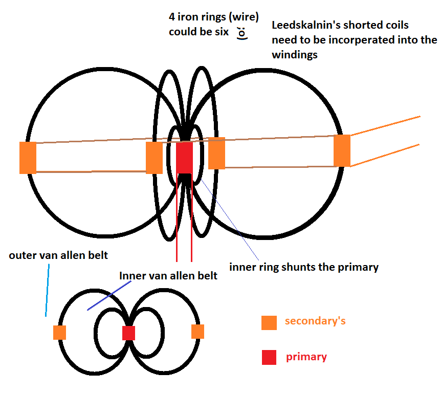
                      • If we are going to build this lets build it right
                        I thought of this, thought I would share
                        I have some florist wire Im going to start winding this today

                        God's beautiful creation is the model Juno - Science:Magnetosphere
                        Last edited by Dave45; 11-16-2012, 01:52 PM.
                        Half of the Answer is knowing the right Question

                        Comment


                        • Kurt if you used wire just a few turns smaller than your outer rings wrapped under the primary it will shunt the primary (keeps the input confined).
                          Worth a shot.

                          later
                          dave
                          Half of the Answer is knowing the right Question

                          Comment


                          • Originally posted by Dave45 View Post
                            If we are going to build this lets build it right
                            I thought of this, thought I would share
                            I have some florist wire Im going to start winding this today

                            God's beautiful creation is the model Juno - Science:Magnetosphere
                            Swap it C cores then put each on 90 degrees and it will be fine
                            You also will need to work out with magnetic current flow vectors from primary coils and from secondaries under load...
                            Last edited by T-1000; 11-16-2012, 06:35 PM.

                            Comment


                            • Originally posted by level
                              I took a quick look at Thane Heins' bi-toroid transformer patent, and it appears that in the patent Thane came up with a simpler way to do this than what he showed in his demo video, using just two toroids. Instead of winding the primary on the center common sides of the two toroids, he wound the primary on one of the isolated sides, and the secondaries on the two remaining sides. I am attaching figure 4 from the patent doc. So this would seem to be a simpler way requiring just two toroids.
                              maybe even 3, two for the secondaries and one for primary?

                              also, would a lot be resolved easier if i was inputing pure sine wave 60hz?

                              that would enable negative cycles to be useful, cause im realizing that the off-time in my PWM is wasted time
                              In the beginner's mind, there are many possibilities.
                              In the expert's mind there are few.
                              -Shunryu Suzuki

                              Comment


                              • Originally posted by T-1000 View Post
                                Swap it C cores then put each on 90 degrees and it will be fine
                                You also will need to work out with magnetic current flow vectors from primary coils and from secondaries under load...
                                i like it, this will be interesting

                                also, im thinking that my secondary core legs are too skinny and should be doubled toroids, as you and others have mentioned.

                                plus im going to switch to sine wave and make use of the neg cycles which have so far been left out i think, as the driver is only putting in a half-wave, this is going to be sweet to add negative cycles
                                In the beginner's mind, there are many possibilities.
                                In the expert's mind there are few.
                                -Shunryu Suzuki

                                Comment

                                Working...
                                X