Announcement

Collapse
No announcement yet.

Donald Smith Devices too good to be true

Collapse
X
 
  • Filter
  • Time
  • Show
Clear All
new posts

  • Originally posted by mr.clean View Post
    lol ok, well are you saying you cant replicate this?

    its very simple, and mine can be improved on 100% if you had a dedicated core shape and better than arbitrary turns, along with taking advantage of resonance based on the frequency you are using and inductance of your primary coil...you know the rest.

    anyway it should be simple enough for you to do even with a full bench of other jobs.
    and then you can test it yourself

    i cant guarantee the 2 secondaries will do the same thing if they are both on one side tho,

    but i can guarantee that you will get the same results as me if you make it like mine or like mine but optimized with thicker and higher perm material like metglass, than L1 core legs made from ferrite.

    thats what i plan on next, that and thicker and higher number of turns.
    then put some serious voltage thru... instead of the 2volts you saw in last video
    maybe a pure sine inverter with fan removed, and high uF (30-80uf, or depending on L1 inductance)
    for resonance at 60hz like i used in one of my don smith vids, brought supply current down 50%
    you would prob call it impedance matching, or power factor correction.

    ...but come on, anyway you look at it, when capacitive and inductive reactance match, its ~resonance~

    you can do it man, not that hard, and doesnt take long, i had toroids snapped and coils wrapped in an hour, very hastily, and threw the switch and just kept trying different cap and freq values,
    but can easily use 60hz ac and tune resonant.

    on a past vid i used a trafo with 121mH L1, with 60hz, so i used 60uF (needed 58) and same output, with less input current (based on high impedance at parallel resonance)

    it just seems like you wont believe or trust my readings, so go for it

    and i could still be wrong, that is the reason for these experiments,
    one thing is for sure, with any normal transformer ive used, current goes up in primary when i load it, and when i make sec do more work, the other bulb compromises and dimms both...
    ...here it totally opposite.

    have you not witnessed this yourself in your own work?
    Right from the start i knew there was something special here, do you not agree these are strange but good behaviour?

    @ LEVEL

    Mr Clean is correct in his findings. Try it for yourself. It's easy.
    Comment


    • Originally posted by clarence View Post
      Hello Mr Clean:

      clarence here,

      Have been silent but watching as always! I need some info from you concerning your supply source for the capacitors you use. I have noticed in your past posts some small red , sometimes blue , etc small radial type I believe are ceramic caps? I have been finding it difficult to obtain a few last ceramic type caps of uf high voltage say 3000v or + value to finish out my invertor driver, so I was wondering what your source is to see if it was any better than the ones I have found. would appreciate a blast back and maybe I can make some progress. thanks a bunch, LOL and best regards on your projects also,

      mike, onward!
      many can be gotten from digikey, but some and diodes are from amazing1.com, they do tesla stuff, and some are e-bay from china, and some are given from electronics recyclers, hope that helps
      In the beginner's mind, there are many possibilities.
      In the expert's mind there are few.
      -Shunryu Suzuki

      Comment


      • appreciate info

        Originally posted by mr.clean View Post
        many can be gotten from digikey, but some and diodes are from amazing1.com, they do tesla stuff, and some are e-bay from china, and some are given from electronics recyclers, hope that helps
        Hello Mr Clean, clarence again , just to say thanks for sharing and I had forgotten about amazeing.com. thanks again for your time kurt!

        mike, onward!

        Comment


        • Originally posted by level
          Thanks! I'll look it up...
          sweet, and one reputable guy who has done lots with them is JLN Labs...

          Avramenko's Free Electron Pump
          Avramenko's Free Electrons Pump v1.0 by Jean-Louis Naudin
          In the beginner's mind, there are many possibilities.
          In the expert's mind there are few.
          -Shunryu Suzuki

          Comment


          • Some interesting news on Joule ringer thread:
            Important Joule Ringer CrossOver update! Possible Kapanadze like effects. - YouTube

            Comment


            • Hi Mr Clean
              I should have made it a bit more clear,but as your scope is already reading accross a set resistance,i didnt see the point in mentioning that it should be volt over time over ohms.
              EG 1 volt over 1 second over 1 ohm is 1 watt second
              Now because your scope has a set load resistance,it can now read the watt's by volt's over time accross that set resistance.
              Hope this clears things up a little with other's
              As far as takeing into account the unit that is supplying the sign wave-why?
              It has nothing to do with the input power being supplied to the primary coil.
              And if we are looking at the devices input and output,then thats all that should be taken into account.
              To take into account the power consumption of the signal generator would be like saying my car is only getting 10mpg with a 2 ton trailor behind it.
              The power consumption of the signal generator can be eliminated,and a more efficient one put in it's place.

              What has to be remembered is that a single device is under test here,and only the consumption and output of that device should be taken into account.

              When you pay for your power supply to your house,you aint charged for the losses in the line's all the way back to the power station.

              I would sugest removing the LED from the input,and just show the consumption of the primary load.
              As far as converting the ac output to dc,well thats just another loss.
              Just place a resistor accross the output coils,and see what your scope says then.
              Or use the resistor your scope has inbuilt.
              Your scope will then make the calculation's itself to give you your watts-as it did in your video.
              Looking at your scope specs you wrote above,your scope is more than able to make these calculation's.

              Keep up the great work.

              Comment


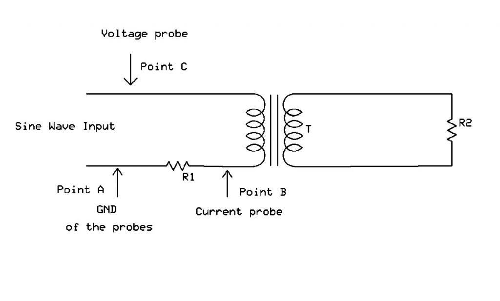
              • Hi all, We do pay for the losses involved in the the supply of the power at the
                socket when we pay our bills, anything other than what the socket provides as in
                frequency ect. will incur more losses, such as the signal generator.

                Anyway without considering the signal generator power I would setup the
                measurement like in the drawing. Mr Clean can you modify the drawing to show
                where you take the measurements with the LED to get the input power
                measurement ?


                I would measure the RMS voltage across R1 at points (A) and (B) in volts then
                divide it by the resistance in Ohms to get the current through the primary,
                then multiply the current by the RMS voltage measured at points (A) and (C) to get the apparent power.

                Then there is the power factor which could only help. Anything less than 1.00
                will mean the real input power is less. Still with such low power levels the
                chance of measurement error is high in my opinion. If you do away with LED's
                and size the resistors properly you can go up in power and see more accurate
                results.

                Cheers

                Comment


                • Guy's I sure he's upgrading this, he has bent over backwards to show the output, even if its just unity its worth exploring.
                  Let's expand, make it larger, larger windings different core configurations then see if we get more.
                  Its a direction worth investigation.

                  later
                  dave
                  Half of the Answer is knowing the right Question

                  Comment


                  • Cold/Hot electricity in Mr. Clean's Bi-torroid?

                    As I am reading all these posts about measuring power from the bi-toroid circuit of Mr. Clean, I have to ask this question...

                    Are we falling into the trap of trying to demonstrate power out via traditional Ohms law when we know that cold-electricity producing circuits can not be measured using Ohms law?

                    Zilano has attempted to teach us that cold electricity is produced from capacitor-based circuits and normal hot electricity from coil-based circuits...

                    A meta-metail/ferrite toroid circuit should be producing cold electricity since the output we are trying to measure appears to be BEMF (back-EMF) - or possibly a mixture of both (one of my theory's anyways ;-) )

                    The output of this circuit is probably gating the same type of energy as Floyd Sweet's magnet-based circuits did.

                    So, if this turns out to be true - none of our traditional power calculations will work on Mr. Clean's discovery.

                    The only way to determine true power out will be to use Power (W) in measurements and then demonstrate power out using a series of loads with known wattage to visually calculate power or perhaps heating of water and measuring with a thermometer.

                    However, there is a possibility that the power out could have high frequency components which do not drive some loads such as incandescent bulbs as does low frequency AC or pure DC.

                    Just for the record, I am a classically trained EE who started working in this area a year ago. I have a Don Smith type circuit lighting a 50W, 120V bulb very brightly and working on the last step of frequency adjustment from 30KHZ down to 60Hz using a 1KW iron transformer.

                    Great work Mr. Clean!

                    Benjamin
                    Attached Files

                    Comment


                    • Originally posted by Farmhand View Post
                      Hi all, We do pay for the losses involved in the the supply of the power at the
                      socket when we pay our bills, anything other than what the socket provides as in
                      frequency ect. will incur more losses, such as the signal generator.

                      Anyway without considering the signal generator power I would setup the
                      measurement like in the drawing. Mr Clean can you modify the drawing to show
                      where you take the measurements with the LED to get the input power
                      measurement ?


                      I would measure the RMS voltage across R1 at points (A) and (B) in volts then
                      divide it by the resistance in Ohms to get the current through the primary,
                      then multiply the current by the RMS voltage measured at points (A) and (C) to get the apparent power.

                      Then there is the power factor which could only help. Anything less than 1.00
                      will mean the real input power is less. Still with such low power levels the
                      chance of measurement error is high in my opinion. If you do away with LED's
                      and size the resistors properly you can go up in power and see more accurate
                      results.

                      Cheers
                      ok i think i follow
                      In the beginner's mind, there are many possibilities.
                      In the expert's mind there are few.
                      -Shunryu Suzuki

                      Comment


                      • Originally posted by level
                        Hi mr. clean. If you are interested, I am attaching a modified version of farmhand's schematic drawing to this email. With your bi-toroid setup, and feeding the primary with a clean sinewave, if you set your scope to read Vrms, measure the four RMS voltage readings exactly as indicated on the attached drawing, and send me your results. Also indicate what the resistance values you use for Rs (should be 1 or 2 ohms at the most ideally) and RLoad in the drawing, and I will calculate the following for you:
                        input power
                        output power
                        power factor
                        efficiency

                        If you are interested, reply back to this email with your voltage measurements and two resistor values and I'll calculate and post the results.

                        V1 = RMS voltage as read across just the primary winding terminals. If you have a capacitor in parallel to the primary winding that should still be ok.
                        V2 = RMS voltage across your sinewave generator terminals
                        V3 = RMS voltage across the series resistor terminals
                        V4 = RMS Voltage across your load resistor terminals. You should use a suitable load power resistor for this test.

                        Don't use any LEDs or lights in the primary or secondary circuits in this test. Just the one ohm series resistor in the primary and the single load resistor. You also don't need to add any diodes or a bridge rectifier in the secondary circuit as well. If you are driving with a sinewave and you just use a resistor for the load in the secondary that will be fine. Also, how are you connecting to your secondary2 when you do your tests? Do you just have a short across it, or
                        what exactly? If you have it in series with secondary1, do you think you can post up a simple schematic of exactly how you have your secondary 1 and 2 wired in to the load, including any capacitors or anything else you have added to the secondary circuits as well?

                        By the way, if your scope probe has a switch on it that allows you to select x1 or x10, it is better to select x10 on the probe, but if you do this you also need to go into the scope configuration and select x10 for the probe in the scope settings as well. When the scope probe is set for x10, the scope probe has a higher input resistance and your scope will give more accurate voltage measurement readings. I will be interested to see what the results are if you are interested in trying this.
                        well sure im interested, but i'll have to get some more resistors

                        lol i know you guys are genuinely interested, but im just trying to get other stuff done at the same time to move ahead, and it just seems redundant until i re-core and re-wire it to do BIG power.

                        but sure i can hook resistors up everywhere on it and do that i think

                        anybody else have a BiToroid working yet who can take on these requests? jokin

                        i think you guys are assuming its more complicated than it is, just signal gen, with cap parallel, and a bulb parallel, and hooked to L1, with scope reading across bulb

                        L2's are just 2 wires coming out of each, and going to their own load, parallel to the bulb, with the scope across the bulb.

                        1khz sine @ 2volts set on gen

                        thats it
                        In the beginner's mind, there are many possibilities.
                        In the expert's mind there are few.
                        -Shunryu Suzuki

                        Comment


                        • Originally posted by bpshell View Post
                          As I am reading all these posts about measuring power from the bi-toroid circuit of Mr. Clean, I have to ask this question...

                          Are we falling into the trap of trying to demonstrate power out via traditional Ohms law when we know that cold-electricity producing circuits can not be measured using Ohms law?

                          Zilano has attempted to teach us that cold electricity is produced from capacitor-based circuits and normal hot electricity from coil-based circuits...

                          A meta-metail/ferrite toroid circuit should be producing cold electricity since the output we are trying to measure appears to be BEMF (back-EMF) - or possibly a mixture of both (one of my theory's anyways ;-) )

                          The output of this circuit is probably gating the same type of energy as Floyd Sweet's magnet-based circuits did.

                          So, if this turns out to be true - none of our traditional power calculations will work on Mr. Clean's discovery.

                          The only way to determine true power out will be to use Power (W) in measurements and then demonstrate power out using a series of loads with known wattage to visually calculate power or perhaps heating of water and measuring with a thermometer.

                          However, there is a possibility that the power out could have high frequency components which do not drive some loads such as incandescent bulbs as does low frequency AC or pure DC.

                          Just for the record, I am a classically trained EE who started working in this area a year ago. I have a Don Smith type circuit lighting a 50W, 120V bulb very brightly and working on the last step of frequency adjustment from 30KHZ down to 60Hz using a 1KW iron transformer.

                          Great work Mr. Clean!

                          Benjamin
                          i appreciate that good point, im not sure about the cold and hot yet, but thats all possibly affecting things

                          it seems to be acting ok on all measurements, everything is up where it should be and low where it should be, matching what im visually seeing with bulbs and reading on meter, and matching the DC setup used previously more or less.
                          (better now with sine)

                          very cool to hear about your Smith work, i'd love to see that !!
                          In the beginner's mind, there are many possibilities.
                          In the expert's mind there are few.
                          -Shunryu Suzuki

                          Comment


                          • does the resistance of the coil itself count?

                            and what about the effects of resonance on resistance?

                            in the drawing the scope probes were in the indicated spot, just with bulb across, but bulbs were not affected while reading so i cant imagine them making a difference, but i'll have to do these tests later today, if the girlfriend can wait Lol
                            Last edited by mr.clean; 11-22-2012, 10:39 PM.
                            In the beginner's mind, there are many possibilities.
                            In the expert's mind there are few.
                            -Shunryu Suzuki

                            Comment


                            • Originally posted by Tinmanpower View Post
                              Hi Mr Clean
                              I should have made it a bit more clear,but as your scope is already reading accross a set resistance,i didnt see the point in mentioning that it should be volt over time over ohms.
                              EG 1 volt over 1 second over 1 ohm is 1 watt second
                              Now because your scope has a set load resistance,it can now read the watt's by volt's over time accross that set resistance.
                              Hope this clears things up a little with other's
                              As far as takeing into account the unit that is supplying the sign wave-why?
                              It has nothing to do with the input power being supplied to the primary coil.
                              And if we are looking at the devices input and output,then thats all that should be taken into account.
                              To take into account the power consumption of the signal generator would be like saying my car is only getting 10mpg with a 2 ton trailor behind it.
                              The power consumption of the signal generator can be eliminated,and a more efficient one put in it's place.

                              What has to be remembered is that a single device is under test here,and only the consumption and output of that device should be taken into account.

                              When you pay for your power supply to your house,you aint charged for the losses in the line's all the way back to the power station.

                              I would sugest removing the LED from the input,and just show the consumption of the primary load.
                              As far as converting the ac output to dc,well thats just another loss.
                              Just place a resistor accross the output coils,and see what your scope says then.
                              Or use the resistor your scope has inbuilt.
                              Your scope will then make the calculation's itself to give you your watts-as it did in your video.
                              Looking at your scope specs you wrote above,your scope is more than able to make these calculation's.

                              Keep up the great work.
                              Hi TinMan great to see you here

                              ok sounds good, i will take off LEDs and re-do all, then take it all apart and put it back together

                              so i can use the built in resistor? oh this is simple, alright i will have a vid within the weekend, but have lots to do.
                              and promised my girl i wouldnt work on stuff this weekend but where there's a will...

                              and thanks, im really trying, and no tricks

                              In the beginner's mind, there are many possibilities.
                              In the expert's mind there are few.
                              -Shunryu Suzuki

                              Comment


                              • Originally posted by T-1000 View Post
                                thanks for this, i like Laser's stuff too
                                In the beginner's mind, there are many possibilities.
                                In the expert's mind there are few.
                                -Shunryu Suzuki

                                Comment

                                Working...
                                X