Announcement

Collapse
No announcement yet.

Donald Smith Devices too good to be true

Collapse
X
 
  • Filter
  • Time
  • Show
Clear All
new posts

  • I managed to saw out one of those computercord ferrites and I need 3 more.

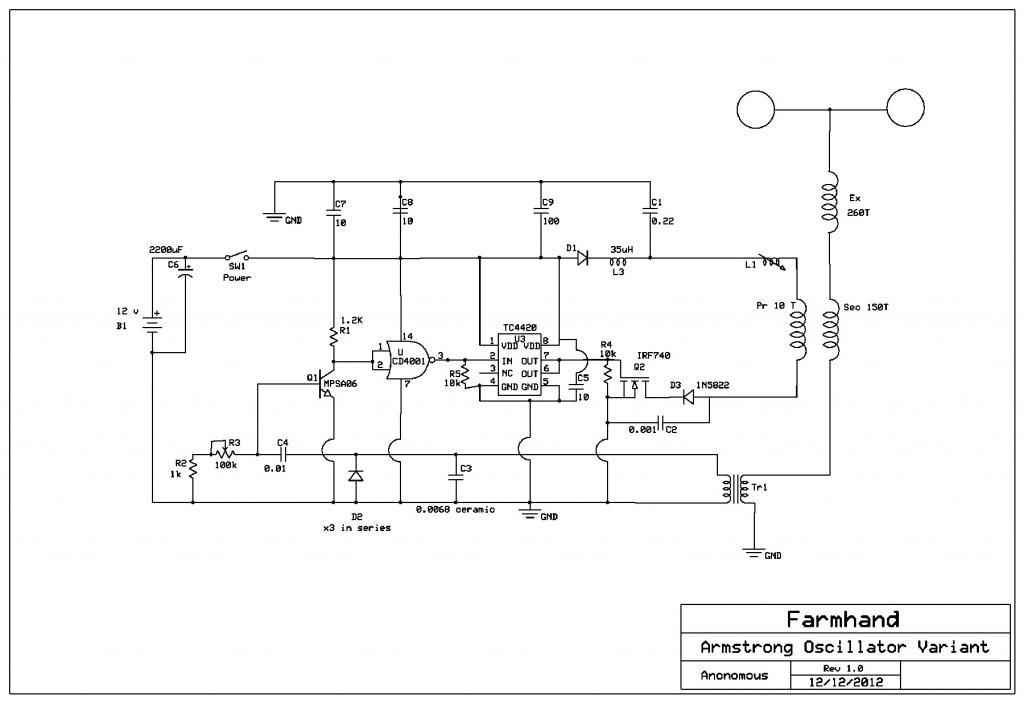
    I'll put 2 primary windings on it, equal in length. One with thin wire that will drive the coil to resonance an one with thick wire to harvest the current.

    On the secondary I will put the longest winding that I can get on it.
    This is the resonant winding.
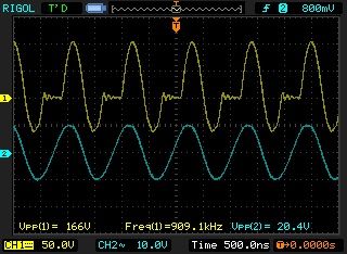
    And KHz, defenitly.

    But I still need to proove that my ignitioncoil works before I do something else.

    Comment


    • Originally posted by T-1000 View Post
      2) It is shorted coil. What happens to transformer frequency when secondary coil is shorted? It goes all way to resonant ringing!
      Saturated coil can always be fixed with a larger capacitor.
      Last edited by janost; 12-12-2012, 09:25 AM.

      Comment


      • You definitly dont want saturation anywhere in a coil setup.
        Saturation is like the magnetic version of DC-current.
        Last edited by janost; 12-12-2012, 09:26 AM.

        Comment


        • This should oscillate the coil spot on resonance.
          Attached Files

          Comment


          • Originally posted by janost View Post
            This should oscillate the coil spot on resonance.
            hehe cool

            careful though... you may end up with this

            http://www.free-energy-info.co.uk/DonSmith/Don25.gif
            In the beginner's mind, there are many possibilities.
            In the expert's mind there are few.
            -Shunryu Suzuki

            Comment


            • hookup how?

              Originally posted by mr.clean View Post
              hehe cool

              careful though... you may end up with this

              http://www.free-energy-info.co.uk/DonSmith/Don25.gif
              hello Mr Clean,

              clarence,

              never have given it much thought before- but do you or anyone know how this device hookup would be implemented. as you say that type circuit would be a definite CAREFUL!! just wondering what your thoughts and advice would be for a possible hook up and implementation.

              good to post with you again, have been busy on the Hendershot Gen thread with Dave, GSM, and others besides continueing on my own DS build. thanks for your thoughts Sir, when you get a chance. LOL

              as always, mike, onward!

              PS: the Hendershot is a winner I believe, and I like it because it has no battry. you might be suprised where the start up comes from. sooner or later all paths lead to T.
              Last edited by clarence; 12-12-2012, 06:01 PM. Reason: PS

              Comment


              • Originally posted by T-1000 View Post
                It got several functions. Here is few I could spot on:
                1) It is capacitor plate. The second capacitor plate can be flat coil or similar
                2) It is shorted coil. What happens to transformer frequency when secondary coil is shorted? It goes all way to resonant ringing!
                3) The coils and capacitor (1.) are on same magnetic path arrangement. If thery are part of ballast LC coil you got connection on magnetic level between coil and cpacitor.

                And for final word I will add quotes from Lester Hendershot (1928-1960):

                "Magnetism must be cut. The lines of force circling the earth are constant and if this force is broken up, and polarized, you have equivalent of uranium broken up, which creates heat and in turn creates power"
                "A very small unit composed of wire, a magnet, serveral especially designed coils, condensors(capacitors edt. note), collector units, and a few other minor items, will cut this force. Another especially designed mechanism will polarize it, giving positive and a negative connection to any resistance and the result is the generation of electricity."

                So if you manage get to the point where magnetic fields will be manipulated the result is power generation...
                i agree, coil shorting is very good, right now i am stuck between shorting one secondary or using both secondaries... the effect is that close!

                may be off topic, but could you translate this? would be much appreciated
                Вечный двиготель - репликатор Капанадзе!!! - YouTube
                In the beginner's mind, there are many possibilities.
                In the expert's mind there are few.
                -Shunryu Suzuki

                Comment


                • My oscillator failed or sort of failed.
                  It has to high impendance so it doesnt drive the coil with more than 1.5v.

                  I need to make one with a mosfet or 3055 NPN.

                  Comment


                  • Originally posted by clarence View Post
                    hello Mr Clean,
                    ... Yo

                    Q just wondering what your thoughts and advice would be for a possible hook up and implementation.

                    A... if you mean the transistor circuit with magnetostrictive rod, i shamefully haven't even tried it yet but it should be pretty easy by the looks of it...
                    Originally posted by clarence View Post
                    PS: the Hendershot is a winner I believe, and I like it because it has no battry. you might be suprised where the start up comes from. sooner or later all paths lead to T.
                    ... thats cool! can you point me to a good replication tho, i was looking for Hendershot stuff and maybe i just got sidetracked, but id love to see one, and a more detailed shematic? if possible.
                    anyway i like the coil, schematic was a bit confusing tho, but the symmetry of the circuit is attractive, and the magnet thing is very cool
                    Last edited by mr.clean; 12-13-2012, 12:10 AM.
                    In the beginner's mind, there are many possibilities.
                    In the expert's mind there are few.
                    -Shunryu Suzuki

                    Comment


                    • Farmhand vid

                      Dude you are way too modest!!

                      everyone here wants to see this kind of stuff!
                      you do great work! and you dont even post it

                      great stuff man
                      Two Receivers and Armstrong Oscillator Transmitter - YouTube
                      In the beginner's mind, there are many possibilities.
                      In the expert's mind there are few.
                      -Shunryu Suzuki

                      Comment


                      • Originally posted by janost View Post
                        My oscillator failed or sort of failed.
                        It has to high impendance so it doesnt drive the coil with more than 1.5v.

                        I need to make one with a mosfet or 3055 NPN.
                        dont worry you'll get it by the sound of your determination,

                        and hey if you are looking for a reliable oscillator, Mopozco used a Royer oscillator in this vid... and many others i think, his TR.OS. (transistor oscillator)

                        TROS -- Don Smith I "spark gap" rectifier - YouTube

                        always motivating to watch his stuff
                        In the beginner's mind, there are many possibilities.
                        In the expert's mind there are few.
                        -Shunryu Suzuki

                        Comment


                        • Index of /ftp/Inventors/Hubbard-Coil
                          Free Energy Hubbard Coil
                          Last edited by Dave45; 12-13-2012, 02:41 PM.
                          Half of the Answer is knowing the right Question

                          Comment


                          • very cool, ive never seen this Hubbard stuff,
                            but makes a lot of sense being series as illustrated, now im thinking of putting series caps on my Smith secondaries as well and see if anything changes
                            The Hubbard would be a fun 1 hour build
                            hmmm...

                            and excellent picture ability, but one thing i think i saw is the bottom ends of the Hubbard secondary coils connect to the next top,
                            possibly taking advantage of a strange mix of parallel bifiliar wound / series connected effect due to the proximity? idk maybe
                            Last edited by mr.clean; 12-13-2012, 06:46 PM.
                            In the beginner's mind, there are many possibilities.
                            In the expert's mind there are few.
                            -Shunryu Suzuki

                            Comment


                            • Remember that at resonance a series circuit is a short and the input current skyrockets. So does the voltages over the inductor and cap.

                              Feeding 10mA into a series resonance with Q=100 makes the current drawn 1A

                              In a parallel resonance the voltages stay the same but the current circulating multiplies and the impendance climbs instead.

                              Feeding 10mA into a tank circuit with a Q=100 still draws 10mA but the circulating current equals 1A

                              Comment


                              • Here's a shot of the mosfet drain (yellow trace) which is the negative
                                end of the primary, of the circuit in the video Mr Clean linked for me, thanks Mr Clean

                                With 12 volts supply and about 300 mA = 3.6 Watts I get 160 volts or so
                                across the primary. A 160 volt pressure facing a resistance of 1 Ohm should
                                produce a peak current of 160 Amps in the primary with 300 mA input current
                                at 12 volts.

                                The childs swing analogy can be seen there, the push happens on
                                the way up at the zero volts point. I think for better efficiency the primary
                                secondary coupling should be as close as possible (to allow good energy transfer)
                                and the free oscillations happen in the extra coil, the output is actually the
                                bottom of the secondary which drives the receivers by the currents between
                                the transformer bottom secondary terminals.


                                This is the circuit diagram. It's an Armstrong oscillator variant.


                                Cheers
                                Last edited by Farmhand; 12-13-2012, 10:15 PM.

                                Comment

                                Working...
                                X