Fly Back Driver
Hello Gedfire,
YES YES it is good to be back and to hear from you! loved your input!
@ ALL
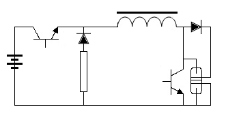
am working on my Driver first (post #10424 circuit shown) - I got a 30kv 20ma 15k-60kHz FLYPVM500
from Information Unlimited - and stripped the primary and utiliy coils off and rewound primary (80 turns) and utility (40 turns) both with #26 silver coated
teflon insulated wire. am now determining the induction uf for primary and utility. will find capacitance for parallel on primary to set driver at 32 KHZ.
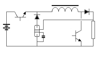
the zener diode with the resister shown in the driver circuit serve as a voltage limiting action to keep the battry supply from going OVER 12 volts!! I found out the hard way in the past that any 12v battry puts out (fresh battry) 13.75 volts
and that EXTRA VOLTS ABOVE 12v IS WHAT HEATS UP THE 2n3055 transistor!!! at or under 12 volts it WILL run cool!
I finally read the specs on the 2n3055 and it said 12 VOLTS ONLY!!! BINGO.
Ben Krasno video and Josef Bogin info which are part of my driver circuit now limit the BEMF across the transistor to keep it from over volting also!
I am only looking for a low voltage of 360 v output by my driver. that across my L1 will give me 2400 v (aprox) thru my L2. (later I will add the second L2 receiver next to this DIPOLE setup to supply my residential household transformer.
WORKING!


BTW : GED & ALL the thumbnail SHOWS an excellent place to calculate whatever coil info you could need -type the thumbnail info into your search box and upload it - then I click on the HELICAL COIL on the home page!!
as always, mike onward!
Hello Gedfire,
YES YES it is good to be back and to hear from you! loved your input!
@ ALL
am working on my Driver first (post #10424 circuit shown) - I got a 30kv 20ma 15k-60kHz FLYPVM500
from Information Unlimited - and stripped the primary and utiliy coils off and rewound primary (80 turns) and utility (40 turns) both with #26 silver coated
teflon insulated wire. am now determining the induction uf for primary and utility. will find capacitance for parallel on primary to set driver at 32 KHZ.
the zener diode with the resister shown in the driver circuit serve as a voltage limiting action to keep the battry supply from going OVER 12 volts!! I found out the hard way in the past that any 12v battry puts out (fresh battry) 13.75 volts
and that EXTRA VOLTS ABOVE 12v IS WHAT HEATS UP THE 2n3055 transistor!!! at or under 12 volts it WILL run cool!
I finally read the specs on the 2n3055 and it said 12 VOLTS ONLY!!! BINGO.
Ben Krasno video and Josef Bogin info which are part of my driver circuit now limit the BEMF across the transistor to keep it from over volting also!
I am only looking for a low voltage of 360 v output by my driver. that across my L1 will give me 2400 v (aprox) thru my L2. (later I will add the second L2 receiver next to this DIPOLE setup to supply my residential household transformer.
WORKING!


BTW : GED & ALL the thumbnail SHOWS an excellent place to calculate whatever coil info you could need -type the thumbnail info into your search box and upload it - then I click on the HELICAL COIL on the home page!!
as always, mike onward!


Comment