Announcement

Collapse
No announcement yet.

Donald Smith Devices too good to be true

Collapse
X
 
  • Filter
  • Time
  • Show
Clear All
new posts

  • Originally posted by T-1000 View Post
    The video is out in the wild now
    International Friends for Tariel Kapanadze working OU!!! - YouTube

    (I am Arunas there)

    Have fun watching and try to understand principles as much as you can. If you will want to replicate this, you need to be human with brains and tools, not just like monkey repeating circuit!
    Hi,

    I have watched the video, I should watch it again... English speech is difficult to understand. Looking at the circuit, one side of the L2 coil is used ??

    Thanks for posting the link!

    Best regards

    Comment


    • Originally posted by Farmhand View Post
      But why do you equate opposite spin direction to opposite winding of the coils ?

      The diagram I posted shows opposite spin direction on the same winding direction
      ie. the same piece of wire wound into a long coil when excited in the middle the current amps go one way the electron volts the other.

      When you put two opposite wound coils end to end they are a mirror image of
      each other and so different to the diagram of Dons to explain it.

      Both coils in my opinion should be wound the same, or one coil cut in the
      middle to make the center tap then when excited in the middle the electron volts go one way and the current amperes go the other.

      Center tap as Dons drawing says.

      Like in the diagram, I don't see opposite spin as you put it needing to have
      opposite wound coils, I see it as needing one coil cut to make two coils and
      the center tap. Like Don instructs to do in one of his video's.

      Cheers
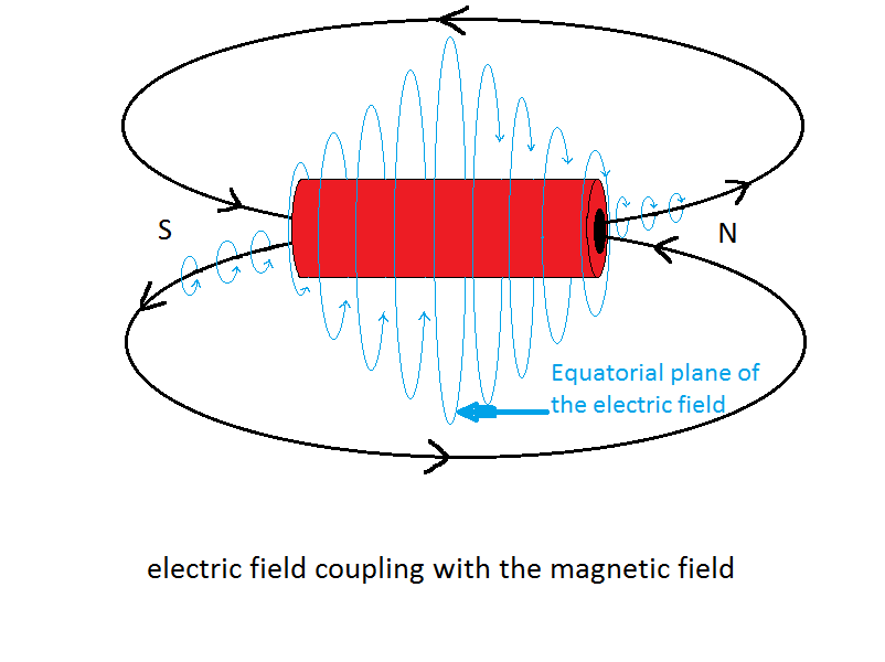
      The reason for the opposing winds is because thats the way the electric field works it moves to the south magnetic field in a ccw direction and moves to the north field in a cw direction.
      The electric field has a neutral plane just like a galaxy has a galactic plane and the particles move away from this plane in oposite spin directions.
      Thats why the coils need to be opposite wound to match the electric field.

      Half of the Answer is knowing the right Question

      Comment


      • Heres the Beef..................

        Wesley says its a done deal TK revealed

        Wesley says its a done deal TK revealed
        ---------------------------

        Wesley quote:
        Well my friends it looks like the history files are being created just right now as we speak... at this very moment... At this very time I'm writing this words.

        Wesley
        Quote:
        Yes I can
        Successful replication of OU device
        150W output around 5 W input.
        By:
        International group of people including me.
        International Friends for Tariel Kapanadze working OU!!! - YouTube


        Wesley
        If you want to Change the world
        BE that change !!

        Comment


        • Originally posted by RAMSET View Post
          Wesley says its a done deal TK revealed

          Wesley says its a done deal TK revealed
          ---------------------------

          Wesley quote:
          Well my friends it looks like the history files are being created just right now as we speak... at this very moment... At this very time I'm writing this words.

          Wesley
          Quote:
          Yes I can
          Successful replication of OU device
          150W output around 5 W input.
          By:
          International group of people including me.
          International Friends for Tariel Kapanadze working OU!!! - YouTube


          Wesley
          Sounds good, is there a particular part in the video I should start at to see the input and output power measurements and/or calculations ?

          Is the input/output measured in the video ?

          That's a C.O.P. of 30 I hope it can be proven by more than assumed power through light bulbs.

          Cheers

          P.S. That's a 20 minute video, and my internet access is limited.
          Dang

          ..
          Last edited by Farmhand; 10-14-2011, 11:24 PM.

          Comment


          • I updated the pic, your right Dons pic shows the same wind and I hate to say it but its wrong.
            Half of the Answer is knowing the right Question

            Comment


            • Wesley is sharing all

              These are the good Guys Cop 30 is just the beginning

              Wesley says its a done deal TK revealed
              ---------------------------

              .
              International Friends for Tariel Kapanadze working OU!!! - YouTube


              There will be much more to come..............

              Chet
              PS
              Farmdude
              The last minute is the money shot [isn't it always?]
              Last edited by RAMSET; 10-14-2011, 11:47 PM.
              If you want to Change the world
              BE that change !!

              Comment


              • Originally posted by RAMSET View Post
                Wesley says its a done deal TK revealed

                Wesley says its a done deal TK revealed
                ---------------------------

                Wesley quote:
                Well my friends it looks like the history files are being created just right now as we speak... at this very moment... At this very time I'm writing this words.

                Wesley
                Quote:
                Yes I can
                Successful replication of OU device
                150W output around 5 W input.
                By:
                International group of people including me.
                International Friends for Tariel Kapanadze working OU!!! - YouTube


                Wesley
                Ok to me it looks like they are trying to claim the discovery of this. The drawing they are showing is almost the same as this one that i posted.
                In fact I think my drawing is better.

                This is just the Tesla discharge method used with the output of a resonant coil system. Looks like maybe a feedback from the load.


                Uploaded with ImageShack.us


                I posted the above drawing here.
                http://www.energeticforum.com/160528-post920.html

                Cheers
                This is a screen capture from the video showing the circuit drawing..


                Uploaded with ImageShack.us

                P.S. I didn't see any output power measurements , and I wouldn't
                trust the digital meters around the spark gap either.

                And this is the Tesla capacitor discharge method of powering a load.


                Uploaded with ImageShack.us

                ..
                Last edited by Farmhand; 10-15-2011, 01:11 AM.

                Comment


                • Well I'm gonna go out on a limb, play devils advocate and say, if there is no
                  reliable output power measurement I can only assume the bulb is lit very
                  efficiently by the 5 watts or less of HF High potential currents.

                  Using HV HF currents can light lights very efficiently with much less power than
                  the regular 60 Hz AC. As Tesla and others have stated many times.

                  I'll reserve my opinion for now. I hope they have gathered extra energy in.

                  Then they will need to explain where the energy came from after they prove the
                  extra energy.

                  Cheers

                  P.S. If I missed the output power measurement I apologize fully and completely.

                  Comment


                  • Originally posted by Farmhand View Post
                    Well I'm gonna go out on a limb, play devils advocate and say, if there is no
                    reliable output power measurement I can only assume the bulb is lit very
                    efficiently by the 5 watts or less of HF High potential currents.

                    Using HV HF currents can light lights very efficiently with much less power than
                    the regular 60 Hz AC. As Tesla and others have stated many times.

                    I'll reserve my opinion for now. I hope they have gathered extra energy in.

                    Then they will need to explain where the energy came from after they prove the
                    extra energy.

                    Cheers

                    P.S. If I missed the output power measurement I apologize fully and completely.
                    I hope they do have it. I really do. But I'm with you on this one Farmhand. Although I don't really care where the extra energy comes from as long as it comes.

                    Comment


                    • Here's the two particles combined

                      when combined they form the electron
                      Half of the Answer is knowing the right Question

                      Comment


                      • Originally posted by Farmhand View Post
                        Then they will need to explain where the energy came from after they prove the
                        extra energy.
                        First at all,ask yourself question: what happens when you charge capacitor with HF impulses and discharge it? And then you charge it again for next discharge cycle for continues pulses?

                        The second thing is - when you have Tesla Hairpin attached to diodes from 1 wire after flyback transformer ,what's happening there? Does it affect the flyback input power if you short hairpin completely? The answer is in open circuit... You can short it, nothing happens and instead of shorting you charge capacitor over there then discharge to TT. Again, no additional power taken except from capacitor itself.

                        Now the next step: As you discharge capacitor into coil, you get induction on secondaries but which coil needs to be used for primary for gathering large magnetic impulse as possible? What type of primary coil in TT should be for shorted secondary coil what does not affect primary coil? The answer is - you make standing wave so load does not affect input. Catch 22!

                        And finally, how you connect load? If you connect directly into secondary, it will make LC circuit what you don't want to have. So how to use it? There's only way - attach diode and capacitor then discharge capacitor overvoltage over spark gap. So another open circuit lol!

                        Have fun on reviving Nicola Tesla work!

                        Comment


                        • Tapping of L2

                          @ T1000

                          Looking at the video schematic, it looks like you guys only tapped one side of L2 and left the other end open. Am I reading that correct & why. Thanks

                          Comment


                          • Originally posted by T-1000 View Post
                            First at all,ask yourself question: what happens when you charge capacitor with HF impulses and discharge it? And then you charge it again for next discharge cycle for continues pulses?

                            The second thing is - when you have Tesla Hairpin attached to diodes from 1 wire after flyback transformer ,what's happening there? Does it affect the flyback input power if you short hairpin completely? The answer is in open circuit... You can short it, nothing happens and instead of shorting you charge capacitor over there then discharge to TT. Again, no additional power taken except from capacitor itself.

                            Now the next step: As you discharge capacitor into coil, you get induction on secondaries but which coil needs to be used for primary for gathering large magnetic impulse as possible? What type of primary coil in TT should be for shorted secondary coil what does not affect primary coil? The answer is - you make standing wave so load does not affect input. Catch 22!

                            And finally, how you connect load? If you connect directly into secondary, it will make LC circuit what you don't want to have. So how to use it? There's only way - attach diode and capacitor then discharge capacitor overvoltage over spark gap. So another open circuit lol!

                            Have fun on reviving Nicola Tesla work!
                            I don't have to ask myself any questions, I'm not the one claiming C.O.P. 30.

                            And if I did I would have input and output power measurements.

                            Comment


                            • Originally posted by MonsieurM View Post
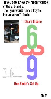
                              Thanks T-1000; If i may add, it is also buried in the schematics of Tesla's Set up
                              isn't it Farmhand
                              Farmhand, notice the endings of each pole..."2 cones" and a " a disc" if viewed sideways

                              Originally posted by zilano
                              Hi,

                              Can you explain the magnificence (history of ideas) of 3, 6 and 9 further?

                              What are 3, 6 and 9 and why do you connect it to Don Smith setup ?
                              (6=ccw, 9=cw and 3=caduceus)

                              Yes I know, lots of questions.

                              Thank you!

                              Best regards

                              Comment


                              • you are asking me to summarize a large volume of information

                                start here: http://www.energeticforum.com/renewa...magnetism.html

                                and here:

                                http://www.energeticforum.com/renewa...-crystals.html

                                and I hope you'll find the answers to your questions
                                Signs and symbols rule the world, not words nor laws.” -Confucius.

                                Comment

                                Working...
                                X