 Tweet
Tweet
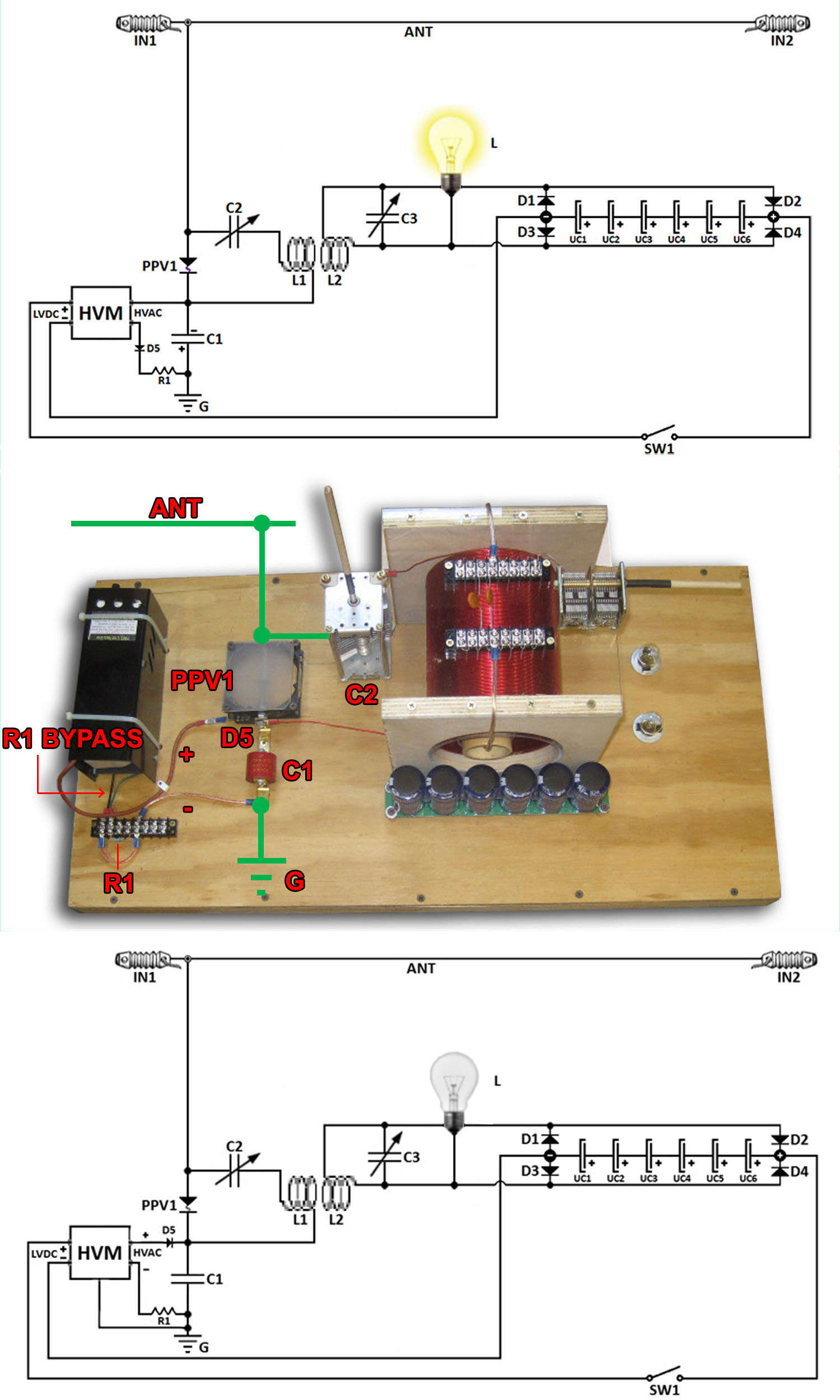
The top circuit is a copy of your wiring.
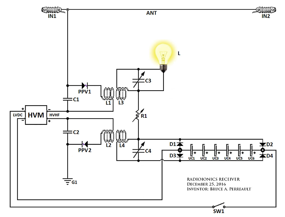
The bottom circuit is the original.
Mwtj has is wired the same as original. If his internal flyback diode is the red lead. It matches Bruce's circuit.
Please bare in mind the resistor is not connected and the earth ground not connected in his picture.
But that is how he had it laid out when it was successfully working. Am I right Mwtj?


Comment