Announcement

Collapse
No announcement yet.

Donald Smith Devices too good to be true

Collapse
X
 
  • Filter
  • Time
  • Show
Clear All
new posts

  • Also with capacitors that have a tolerance of + or - 5% I noticed that two
    seemingly identical capacitor banks can have a different value, which can mean
    a difference of good resonance or not, also the placement of objects in close
    proximity to the coils will also affect them, for instance a hand or other object
    which has capacitance or self capacitance when close to a resonant coil will add
    capacitance and lower the resonant frequency, just like a load can do.

    A variable capacitor means tuning can be precise and when the load changes
    the resonant frequency can be altered to re-tune the device to the load.

    Cheers

    P.S. connecting a scope probe directly to a resonant coil should I imagine
    alter the resonant frequency as well, with hi q setups all these things can be
    frustrating because they can be compounding or counteracting it just
    depends what and where is being affected.

    ..
    Last edited by Farmhand; 11-06-2011, 01:58 AM.

    Comment


    • LC tank resonant circuit vs natural coil resonance.. I bet it is better to find out natural resonance because this is where you hit maximum effect, especially for Tesla Coil primary after SG..

      P.S> You can educate yourself about it, please see my post on http://www.energeticforum.com/renewa...tml#post165547

      Comment


      • Dons setup uses a tank circuit for the reason that in my opinion for natural
        resonance the coils need to be perfectly tuned length, also for natural
        resonance more wire is needed for lower frequency and without a primary
        charging capacitor the energy though the coil with each bang is much less,
        that is compensated by buku frequency like 40 mhz or something but that is
        almost unusable for full effect. What kind of bridge rectifier can rectify 40 Mhz
        AC ? And the higher the frequency the less it take's to de-tune. The practical
        way is to use a charging circuit/capacitor. Also with natural resonance and no
        capacitors no tuning is possible unless to shorten or lengthen wires. Don used the tank
        circuit because it is the most practical way.

        Anyway to use natural resonance is much more difficult, Tesla stated the
        capacitor in his primary charging circuit is to magnify the current in the
        primary circuit.

        On another note has anyone got the CW-CCW coils working yet ? Maybe if we
        find out which way the secondary coils are wound in an NST it will tell a story.

        I think the CW-CCW setup will produce opposite polarities out of phase and cancel when
        summed together but I can't be certain. But I think CCW-CCW coils will
        produce same polarity but out of phase and be additive.

        And I think Tesla's Oil coil which was wound CW-CCW had two primaries also
        CW-CCW and so produced opposite polarities but in phase for double voltage.

        Cheers

        Comment


        • CW and CCW Coil

          Is it possible to do the coil udjustable maybe so that it can be adjustable to resonance? Just an idea

          Comment


          • Coil Adjusting for Resonance frequency change.

            Hallo. Guruji
            Guruji
            CW and CCW Coil
            Is it possible to do the coil udjustable maybe so that it can be adjustable to resonance? Just an idea
            I think its very possible tot adjust de number of turns of your coil .. even half a turn or a tenth of a turn makes a different in the inductance of the coil and therefore also in the resonance frequency of the coil.
            Also changing the length of the coil ( more or less space between de windings ) makes a different in the inductance and therefore also in the resonance frequency.

            Here You can calculate the inductance of an Air Coil.
            Here you can calculate res.freq. etc. of LC circuit

            These examples are calculated with a capacitance of 0.2 µF being 200nF

            Example varying Turns of a Coil.
            Ø inch. Length inch. Turns ind µH. Res fr kHz
            3.........1................4.........1.532....287
            3.........1................4.5.......1.939....255
            3.........1................4.75......2.160....242
            3.........1................5..........2.394....230
            3.........1................5.1........2.490....225

            Now varying Length of Coil
            Ø inch. Length inch. Turns ind µH. Res fr kHz
            3..........1...............5........2.394.....230
            3..........2...............5........1.679.....274
            3..........3...............5........1.293.....313

            I believe in abundance and happiness

            Comment


            • Replication!!!!

              From Over unity thread
              From here

              Selfrunning Free Energy devices up to 5 KW from Tariel Kapanadze


              energia9

              Quote
              i have experimented, things are happening the exact way aidas, arunas, wesley say, no theories will make your device work! DO IT and you will know!!!
              everything has to be adjusted piece by piece, you will not suceed with a fixed thing....

              trust it, the phenomenon is not explained in conventional science, and media will still try to supress it although it can be reached by anyone this time.
              All physics books needs either adding more info or completely rewriting...
              If you want to Change the world
              BE that change !!

              Comment


              • Hi Guys, Yes of course it is possible to adjust the resonant frequency of a coil by
                adjusting it's turns or turn spacing, but can that be done after the device is built
                to compensate for changing conditions and loads ? With variable capacitors
                mainly primary this can be done while the setup is powering a load. Saving a lot
                of trial and error. Don only seemed to demonstrate fixed loads which would
                require no tuning. That is a given if the load never changes the tuning need not
                change. With some tuning available while the setup is running if a bulb blows the
                setup could be tuned to compensate. My experiments tell me that if I load down
                the output capacitor after the FWBR or unload it the resonant frequency of the
                secondary changes.

                I imagine even relative humidity could change the tuning of a resonant coil
                especially one at Mhz frequency.

                Same thing with most of these devices that rely on resonance, connecting a
                load or another load can bring the system into tune and increase input and
                output or put it out of tune reducing input and thereby reducing losses and
                also reducing output.

                I'm gonna go out on a limb and say Dons device is nowhere near as useful as
                it looks or is made out to be. It requires careful tuning of the components
                values under the desired load, I imagine Don used variable capacitors to
                determine the correct capacitance for his primary and secondary under the
                desired load then used the capacitance value to give a bit of leeway for the
                load to bring the system into tune when the input voltage fluctuates, if the
                input voltage drops a bit then so will the output voltage so the fixed load will
                load down the output caps changing the resonant frequency of the secondary
                coil, basically if the input voltage drops the fixed load will be seen by the
                system as an increased load. In my opinion, going by my experiments with a
                slightly different resonant setup, any change in the load will affect the
                resonant condition and any change in input power will be an effective change
                of the load. Different loads have different effects. With a fixed load and fixed
                input things should stay pretty good unless there is a change in the near
                vicinity of of the coils.

                The higher the Q of the system and the higher the operating frequency the
                more pronounced the effect will be.

                This is a video showing the effect of connecting a second load, what I don't
                show in this video is that a simple adjustment of the primary capacitance will
                bring the setup back into tune and the output and input would increase as it does.

                Reduced input current under added load effects 33 - YouTube

                And this one shows the way the field can be loaded and affect resonance.
                Just ignore the comment about the BEMF, it was a off the cuff remark and not
                entirely true. But the effect can be seen, anything in the field will add
                capacitance to the coil and lower it's resonant frequency. Again adjusting the
                primary capacitance rematches the primary secondary resonant frequency.
                Which I did not show as it was not the point of the video.

                Reduced input current with load.wmv - YouTube

                I only made the video's to show the effect, there is nothing special about it
                and no mystery. That pair of Tesla coils has taught me so much in the last
                few months I can't begin to tell it all. But it's all in the noggin for when I need it.

                Cheers

                Comment


                • anything in the field will add
                  capacitance to the coil and lower it's resonant frequency
                  .
                  hence Tesla meticulous circuit drawings
                  Signs and symbols rule the world, not words nor laws.” -Confucius.

                  Comment


                  • Sooo true

                    I tried a couple of attempts at two of Don Smiths efforts.... to well hidden, The unit Ramset is directing you to look at is an advancement on this TARIEL KAPANADZE EVERYTHING .. WE KNOW FOR NOW..swf - YouTube which of course is a cousin of Tesla's and a close relative to what Don is tempting you with.
                    The difference is because of a bungled “hit” on Tariel and his friend Wesley they have decided to totally “spill the beans” This is not experimental it is Improvement and replication and has now been repeated several times by different “cells” in different countries
                    This has all been carried on at overunity.com. I would respectfully suggest that you temporally “prostitute yourself s” and go flog your bodies over there and pick up the story about here Selfrunning Free Energy devices up to 5 KW from Tariel Kapanadze
                    If I don’t miss my guess I think the missing Technology to bring one of Don Smith contraptions into operation is fully explained, I think particularly of the one with the inverter and the HV neon driver
                    although you will see TK has used a centre tapped(?) oil fired ignition.
                    Anyway although this team have engineered forward to such a point that they are using a ferrite core, As I still have all the components from my Don Smiths effort I would be delighted to be allowed to join you folks on a build of this earlier model (without the ferrite).
                    You actually need the information from about where I have indicated from OU.com. However as you will find out OU.com and their posts have been under constant attack and some posts are missing , however the Information I have indicated is VITAL , be advised to copy what you can....
                    As a Bonus the team has come over to join us on this forum from OU.com in order to replicate their success.. .However I'm sure if we are prepared to put a little effort into learning what we can of the principles they are demonstrating and explaining and asked nicely they wouldn't mind helping us to get getting the earlier Smith/Tesla/Tariel incarnation going.
                    Of course as you will quickly realise their principle concern is to get as many replications of this tried,tested,working machine knocked out. T1000 already helping ... gonna fly!

                    Originally posted by RAMSET View Post
                    From Over unity thread
                    From here

                    Selfrunning Free Energy devices up to 5 KW from Tariel Kapanadze


                    energia9

                    Quote
                    i have experimented, things are happening the exact way aidas, arunas, wesley say, no theories will make your device work! DO IT and you will know!!!
                    everything has to be adjusted piece by piece, you will not suceed with a fixed thing....

                    trust it, the phenomenon is not explained in conventional science, and media will still try to supress it although it can be reached by anyone this time.
                    All physics books needs either adding more info or completely rewriting...
                    Last edited by Duncan; 11-07-2011, 05:41 PM.
                    Whatever you can do,or dream you can,begin it.Boldness has genius,power and magic in it.Begin it now.

                    Comment


                    • Excellent Stuff

                      Thanks FarmHand,

                      I deeply appreciate the comprehensive response.I knew intuitively that there was much more to this than meets the eye.


                      I am actually preparing to buy some variable caps with the widest range or even constructing or purchasing varibale inductors.But I have to be sure as money is kinda rationed with me.This entire thing ,I believe ,is possible and is in the province of Radio Electronics.

                      To fully understand everything I had to go back to veiwing the construction of earlier radio receivers.The ones that used no battery.I found remarkable similarities between those simple circuits and DON/ZILANO circuits.
                      Crystal radio - Wikipedia, the free encyclopedia

                      The Inductive Coupled Receiver is my best bet.So we are constructing High Voltage Radio transmitters and receivers using spark gaps and tesla coils.

                      Those early batteryless radio used variable inductors and variable capacitors all the way.Only the later versions eliminated the variable inductor because of expenses.(Kelly suggested Rheostats in his pdf)

                      So in planning to construct Zilano device I have agree with you that variable capacitors or inductors are highly likely in both tank circuits just like a radio.

                      I have made observations with a regular radio that has a tuner, my car radio digtal tuner and my phone radio and found out that signal is affected by location, body proximity and other radio stuff.

                      I am theorising that that Don used variable capacitors to get perfect resonance then disconnected it.Then he measured its capacitance after which he would order FIXED capacitors custom made! Notice Don does uses variable capacitors and inductors in his earlier devices. See his pdf.He also used them on the multiple receiver device.

                      In designing the Don / Zilano Device without the hassle of precise wire lengths ( which Don suggested but did not seem to use), I think variable caps in the nano and pico farads range are the way to go (and possible inductors).Also stay as close as possible to early radio receiver designs that used inductive coupling but just add a spark gap,more diodes and HV caps.

                      Having a PERMANENT frequency counters (or connect two similar meters simultaneously and temporary of course ,I think scopes have some dual measuring probes ) attached to both tank circuits should counteract the frequency changes due meter attachment and detachment should not matter.Although the values when using the same meter should be constant hence can be compensated for when tuning.

                      We might need to protect these counters (optional and if used) from High Voltages.The circuit could be made self tuning and/or have something to prevent any shift in frequency due to external conditions.

                      Then you could have your ultimate energy device.

                      Using a function generator as suggested by Farmhand ,I believe would help considerably in setting stuff up.Notice Don had a photo with severval meters beside the device.I think I saw a scope,function generator, handheld meters,frequency probe among others.So FarmHand I agree with you on this.

                      After all this, I think my next step is to reanalyse the entire forum and construct a general outline of what I plan to do then :"make it".

                      Thanks again for the help.

                      Regards,
                      Ged

                      Comment


                      • Variable Caps Needed

                        Originally posted by Farmhand View Post
                        You could get lucky and find just the right caps to do the job but the chances
                        are slim unless the coils values can be determined before winding them.

                        Cheers
                        Hi All, FarmHand,

                        Just to say that we know the Barker Coils Don used came standard.Hence they had similar values with some variations with individual coils.So again I agree variable caps are needed.THIS I think is one of the reasons for the vast amount of failures.Kapandanze/Zilano/Don preached that achieving resonance is key.

                        Like in your comment above I was planning on winding all my coils with appropriate wire first,then measuring and calculating approximate resonant caps then buy variable ones with the widest ranges so I can fine tune later.Then I would get/build a function generator ,get another DMM that measures frequency or borrow a scope then tune the device.It would be sweet to see both tank circuits showing the same frequency on the digital readouts...

                        Ged

                        Comment


                        • Hi Guys, Your welcome Gedfire, in my experience it's not the actual frequency
                          that changes, it's the frequency the secondary coil is resonant at, the actual
                          frequency remains constant as far as I can tell, only the coil is affected so
                          that the frequency it becomes resonant at changes so the actual frequency
                          of the primary oscillations is no longer a match to the resonant frequency of
                          the secondary.

                          The resonant frequency being the frequency required for resonance of the
                          secondary and the actual frequency being the frequency the device is
                          operating at.

                          Have you seen video or picture's of Zilano's device. If not how do you know it exists.

                          Duncan I won't be building the T1000 device for various reasons. The main
                          one being no measurement of output power. I'm not concerned if it is OU or
                          not, I won't be building something as an OU device on the basis of it lighting a
                          bulb, ever. I'm not sitting here waiting to build every device someone says is
                          over unity, I have my own plans for my own devices and quite frankly I don't
                          believe the claims. If some believable measurements were made and showed significant
                          gains maybe I would. But I refuse to just believe, which means I can be neither
                          right nor wrong, I don't believe the suppression part either so in my opinion
                          the inventors should clear up any confusion and lack of details. As well as
                          refine their own invention before asking people to replicate it. This is my
                          opinion and I owe no one any explanations for my opinion and I am fully
                          entitled to my opinion and to express it, so I will not be arguing my opinion.
                          I don't refute the claims I just don't believe them. For example they say 150 watts
                          output but it's not measured. And hint a Kw with a spark gap but I didn't even
                          see a demonstration of that 1 Kw performance how did they determine the
                          1 Kw ? Maybe by lighting up 6.666 x 150 watt bulbs to a certain degree if so I
                          didn't see it.

                          I have more than enough to keep me busy with my own devices and study.
                          At this point I see no reason for me to build the Don Smith device either but I
                          might when I think I have the time to devote to it.

                          Regards

                          Comment


                          • Found that out with ordinary radios

                            Originally posted by Farmhand View Post
                            Also with capacitors that have a tolerance of + or - 5% I noticed that two
                            seemingly identical capacitor banks can have a different value, which can mean
                            a difference of good resonance or not, also the placement of objects in close
                            proximity to the coils will also affect them, for instance a hand or other object
                            which has capacitance or self capacitance when close to a resonant coil will add
                            capacitance and lower the resonant frequency, just like a load can do.

                            A variable capacitor means tuning can be precise and when the load changes
                            the resonant frequency can be altered to re-tune the device to the load.

                            Cheers

                            P.S. connecting a scope probe directly to a resonant coil should I imagine
                            alter the resonant frequency as well, with hi q setups all these things can be
                            frustrating because they can be compounding or counteracting it just
                            depends what and where is being affected.

                            ..

                            I also found that there are changes to what comes out of my radio based on my proximity to it and movements of the aerial.The same happened with my analog televison set.

                            Even my cellphone radio is affected based on proximity and movement of the headphone wires that act as an antenna.

                            I am suggesting that maybe an electronic means can be used to compensate for frequency changes due to the proximity effect.I noticed that the researchers at MIT mentioned this problem with their resonant wireless electricity experiments.Hence the Witricity people seem to have found a way to maintain resonance even when moving the receiver and/or transmitter.

                            Thanks to all contributors,as a hobbists,I am now having a better understanding of these devices and is more convinced of its reality.Again, its up to me to make it.

                            Ged

                            Comment


                            • Good to know this

                              Originally posted by Farmhand View Post
                              Hi Guys, Your welcome Gedfire, in my experience it's not the actual frequency
                              that changes, it's the frequency the secondary coil is resonant at, the actual
                              frequency remains constant as far as I can tell, only the coil is affected so
                              that the frequency it becomes resonant at changes so the actual frequency
                              of the primary oscillations is no longer a match to the resonant frequency of
                              the secondary.

                              Have you seen video or picture's of Zilano's device. If not how do you know it exists.

                              I have more than enough to keep me busy with my own devices and study.
                              At this point I see no reason for me to build the Don Smith device either but I
                              might when I think I have the time to devote to it.

                              Regards
                              Thanks for the update.So I should focus on maintaining suitable frequency of the primary.

                              You seem to have done considerable research.Do you mind sharing some of the devices you are working on otherwise?


                              I am gonna attempt a replication of Zilano's version since I have seen numerous results of resonant induction and wireless energy replications.In those replications, resonance is key and has been acheived.The limitation is that no one has used a spark gap,high voltage (I think an electric car company did use high power to charge a car wirelessly) no step up or step[ down capabilities cited and no data on efficiency in terms of multiple receivers NOT loading the primary transmitter.(It is said that radios don't load the transmitter) .So there is something to these devices but time will tell .Like you,I would love to see a video or picture of someone running a HOUSE on one of these devices.A feat not visible in Dons Videos or anywhere else.

                              Zilano has said much,a lot I think and the criticisms and commendations has been plenty but,and I know she has no obligations to anyone but a video or pics would do wonders.

                              Zilanos description of asking the power company to disconnect her supply and enjoying 10kW of power is very tempting especially in my country with

                              US$0.39 per kilowatt!

                              Ged

                              Comment


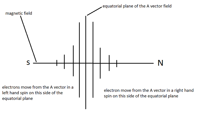
                              • CW/CCW Paths? Or spin?

                                Originally posted by Dave45 View Post
                                The electric field is split right down the middle just like a galaxy has a galactic plane the electrical field has dividing plane,
                                on the north side the electrons move away from the dividing plane in a cw direction
                                and on the south side the electrons move away from the dividing plane in ccw direction.
                                Are you saying that the electrons follow the CW / CCW paths created by the coils? Or are you saying that the electrons literally spin about their own axes in different directions?

                                Comment

                                Working...
                                X