Announcement

Collapse
No announcement yet.

Donald Smith Devices too good to be true

Collapse
X
 
  • Filter
  • Time
  • Show
Clear All
new posts

  • Ahhh I found some light!

    ZZZZ, I found some information you wrote about explaining to drak about how to get cap to fire while in paralell.. Ahhhh so fine!

    No need to reply I just like to understand things before I leap.
    I do not want to look back when I leap.
    Thanks
    Zane


    Originally posted by zilano
    Hi drak!
    spark not firing means u need to adjust caps. wot happns is caps get overcharged and fires (short circuit L) so current flows in primary and energy stored in magnetic field of primary. when magnetic field collapses it induces current in primary which charges cap again. and cycle continues and losses r fed back thru ur flyback to the cap/caps. and cycle goes on endlessly.

    zzz

    Comment


    • Flyback

      Man,

      I have been reading and I'm realizing I need to take this one step at a time. I'm going to start with my flyback.

      zzz...

      can you recommend which of the wound flybacks on this page you would use?


      High Voltage Transformers

      I'm happy to wire up the driving circuit, but I don't want to wind it myself. Thanks!


      J

      Comment


      • Zilano did you every post any pictures or videos of your system running and powering some load?

        Irregardless you seem to have a lot of patience answering the same questions repeatedly and are very open and helpful, thanks for that.
        Last edited by broli; 09-04-2011, 10:51 AM.

        Comment


        • Your bifilar resonating coil is it wound and connected like the attachment below?

          In this thread somewhere there was a statement about the ground forcing a node. Since your bifilar coil is one wavelength long and you force a node in it's middle it means nodes will form at the beginning and end as well. This will cause 0 voltages on both these ends, so it has no use connecting a capacitor or even the ends together. Or am I wrong about this?
          Attached Files
          Last edited by broli; 09-04-2011, 07:04 PM.

          Comment


          • Is there a reason why you're using the term "bifilar" then. It seems you have one 1/4 wave primary and two full wave secondaries left and right of it. bifilar refers to a way of winding and hooking up a coil, usually by winding a turn of one coil between the turn of the other coil like illustrated above. And also with this correction of yours my remark still stands. Since the "bases" of the secondaries are at 0 volt and they will force a node of the standing wave, which also means nodes will form at the ends of the coils. Thus there will be no voltage there.
            Last edited by broli; 09-04-2011, 08:02 PM.

            Comment


            • I don't get the whole theory behind why or how one generates voltage and the other current or how it becomes a 1/4 wave resonator while it has a full wave length. Because tesla used both 1/4 wave length for primary and secondary.*

              But that diagram is more clear, so thanks.

              The thicker the secondary, the more current can be allowed, the stronger the field, the more output you can generate?

              *sorry this statement is wrong**
              **boy this is getting confusing, in tesla's patents he only speaks about 1/4 wave length
              Last edited by broli; 09-04-2011, 09:21 PM.

              Comment


              • zilano

                Forgive me ,I have a black hole in my mind
                So each coil of that pair is 4*1/4 wavelength long and this wavelength is resonant frequency of primary RLC oscillator ( which length is 1/4 wavelength btw) ? Still don't get it why each secondary is 4 times longer then primary - why not the same length as primary ? . Doesn't it mean each secondary has different resonant frequency then primary ?
                I think I could learn procedure but I'm rather interested in understanding why that is working that way.

                Comment


                • Originally posted by zilano
                  HI Boguslaw!

                  well the idea is primary is 1/4 wavelength and secondary each is full wavelength. coz we want over unity output. and we want to fetch full power of one wave. not 1/4. we r here leveraging power to move a load of full wave with just quarter input. We just tap with 1/4 to produce full wave! its like 4 cents in and 1 dollar out!

                  rgds

                  zzz
                  Well, lambda is the same for primary and secondari but the primary is 1/4 of lambda,
                  Thats means the freqvencies is the same in primary and secondary?
                  I better use L1xC1=L2xC2 !?
                  Last edited by nico; 09-04-2011, 10:32 PM.

                  Comment


                  • Spark Gap Placement

                    I'm confused about the location of the spark gap. I have several schematics and drawings and they show different arrangements.
                    Does the SG go in series or parallel to the coil?
                    Does the SG go before or after the capacitor?
                    Does the capacitor go in series or parallel?
                    Does it matter?
                    TIA

                    Comment


                    • electron spin

                      thats correct Z, the electron spins into one coil as amps, and into the other as volts when center tapped between the two...very significant. the fun part is combining the two again for real useful energy. amps x volts = watts.

                      E1

                      Comment


                      • Originally posted by zilano
                        Hi Pendar!

                        see pic!


                        use same positoon of spark gap in don setup. it works for any frequency. it just triggers hv hf to trigger primary coil.

                        rgds

                        zelina
                        Thanks. That helps.

                        Comment


                        • Originally posted by energy1 View Post
                          thats correct Z, the electron spins into one coil as amps, and into the other as volts when center tapped between the two...very significant. the fun part is combining the two again for real useful energy. amps x volts = watts.

                          E1
                          Hello energy1,
                          can you name a source for the science of electron spin behavior you describe?
                          I'd like to read more about it, but is hard to find it.
                          In which book or publication did you find it?
                          Thank you

                          Comment


                          • NST and Variac Purchased

                            Hi zzz,

                            I just placed orders for a 120V / 140V Variac and a 4kV 30ma NST. I couldn't find a 4kV 60ma NST, so maybe I need to wait to find another to wire them in parallel. I didn't see any GFCI reset buttons in the picture, so hopefully it's what I need.

                            Since I'm not using the flyback, the signal I have coming out of this will be roughly 4000V @ 60Hz and 30ma. I would think that I'd want the primary coil ringing at 30kHz across the gap cause it's an even multiple of 60Hz.

                            I still don't understand the purpose of the gap on the output side. I'm guessing it's only necessary to dump the high voltage if you are using a low turns primary to a high turns secondary. That gets you down to just about 480V or whatever your target is and then the varistor smooths out the rest.

                            If that's true then the point is that you can go in either direction (step-up or step-down), as long as you dump the excess volts.

                            I was about to purchase some varistors, but I need to double-check... we are talking about clamping voltage, right? What max voltage and amperage should these be rated for? Also, there aren't any varistors that clamp at precisely 480. They clamp @ 475V and 488V. I'm guessing we should use 475V to protect the 480volt caps downstream.

                            Sorry I'm behind. This thread is moving fast. I have lots of catch-up reading to do. :-)


                            J

                            Comment


                            • Flyback circuit

                              Hello all! This thread has been progressing quiet well and Thank you to all who has helped, especially Zilano, Mr. Clean, Don Smith, Tesla, and so many others.

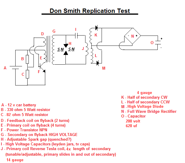
                              This is my current circuit for a flyback system and so far out of all the circuits I tried this one has the best charging time for the capacitor(based off of don's smith circuit, bifiliar). I used a 20 second time trail for comparison but I have no idea how close I am to input compared to output. My multimeter can't read the amps while the system is running due to high frequenicies. Any idea's how to compare watts in to watts out?

                              Also I am curious on how to make this a self running circuit, without the 12volt, seen in the Kapandaze video. I tried some capacitors out front, after the 12 volt, and it helped the circuit to run more cleanly but won't it run after I disconnect the battery.

                              Another question I have is how do I know my voltage on the output? A flyback can operate anywhere from 20kv to 50kv and trying to get it back down to 12 volts seems quiet challenging. Another observation I noticed too was that the ground seem to hinder my charging capacity but when I do attached it to the spark gap, the coil seems to 'shake'.

                              Anyways, thanks to all for your ideas and observations, its inspirational to see great minds seeking to benefit the species. Good show.

                              Just a soul seeking freedom from tyranny.


                              -------------------

                              What lies behind us and what lies in front of us is nothing compared to what lies within us.

                              Comment


                              • @Zilano,

                                Hello, ZZZ;
                                Previously u claimed, u were powering ur house with 10 kW using reverse T. (many turns primary - few turns secondary) together with parallel C and parallel SG. Slowly you moved away from this concept towards the opposite standard one. Now some of us are surely confused: what concept we should believe? especially you are still ignoring all requests to publish at least a photo of your device!
                                Thanks

                                Comment

                                Working...
                                X