Announcement

Collapse
No announcement yet.

Donald Smith Devices too good to be true

Collapse
X
 
  • Filter
  • Time
  • Show
Clear All
new posts

  • Ignition coil frequency

    Your question JoeFR: "can car ignition coil work between 30-35kHz ...."
    Answer: NO - because of the iron core

    Measurement of a brand new standard ignition coil:
    - quite linear behavior up to 5 KHz
    - increasing output voltage up to a considerable resonant point 8KHz
    - at 17 KHz back to the same output like 1 KHz
    - above considerable decrease in output voltage

    Conclusion:
    - Best use for an ignition coil is the resonant point at ca. 8 KHz. We need to exceed 20 KHz (Tesla)
    - Above use transformer with ferrite

    @JoeFR: High quality work! I like it!
    - Seems that you connected the bulb in parallel to the capacitor. What happens if you connect it to the other secondary coil (now open)?
    - Conforming Utkin (see Patrick's online book) the cap performs the required short circuit at the operating frequency. Not shure if he is right. Maybe this coil/cap will run best in resonance mode. Conforming my initial measurements the cw/ccw behaves very unexpected and strange. On the other hand we expect it to not obey standard scinece
    Last edited by JohnStone; 01-25-2012, 10:50 PM.
    Experts spend hours a day in order to question their doing while others stopped thinking feeling they were professionals.

    Comment


    • Originally posted by joefr View Post
      Hi all

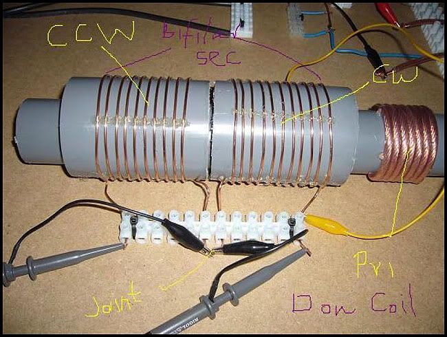
      Today I finished my new Secondary Coil. I wind the same 8 + 8 turn coil but this time in correct order CW and CCW. I used 3.42mm diameter solid copper wire.

      One question: can car ignition coil work between 30-35kHz and put any decent output at this frequency ?

      I will make new video soon because I have to make better adjustable spark gap first.

      JoeFR
      1. I have driven bog standard igntion coils up until nearly 100Khz and they still work on HV lighting experiments.

      For something a little more special here are my two recommendations to try:

      The first one looks like ferrite to me. I used to have one on my 330bhp 4x4 Sapphire Cosworth.

      Ford Sierra RS Cosworth Group A Ignition Coil. | eBay

      MSD Blaster 2 High Power Coil MSD Elec Ign 8202 | eBay


      2. Here is some information regarding an idea for your spark gap. I have some N42 20mm x 20mm diametrically magnetized neodymium if you want to give them a try?

      20mm dia x 20mm thick Diametrically Magnetised N42 Neodymium Magnet (x1) (5060185920826) | eBay

      Also here is some info I dug out of Patricks absolutely amazing PDF with a picture from (sorry cannot find the post, so can't remember your name) earlier in the thread.


      3. For anyone that hasn't seen this 2006 Don Smith video, please watch.

      Don Smith Free Energy - Video

      The link was also courtesy of Patricks PDF.


      4. A nugget from Zilano's posts:

      Since we treat secondary coil as magnet we have to make space for blotchwall (the middle neutral space of N____S middle join.)

      So we make 5 turn_____5 turn ____ is sec coil middle in straight line its length = primary coils total turnwidth. so primary sits between this straight wire joining 5 turns and 5 turns of secondary.

      0000000000000 ___ is joining secondary turns below

      0= Secondary Coil Turns

      0 = Primary Coil Turns (slidable)


      5. JoeFR why has your primary got all those turns?

      I thought the primary was supposed to be 1/4 length of the secondary, therefore the primary should be thicker and chunkier if it is to weight the same.

      *** Am I right in saying the primarys weight should equal one half of the secondary?


      6. Duncan, JoeFR whereabout in UK are you from? I'm from near Plymouth, Devon.
      Last edited by soundiceuk; 01-25-2012, 10:50 PM.

      Comment


      • Originally posted by a.king21 View Post
        Having read Tesla and his teaching re the unsuitability of Hertz waves for energy transmission some clarification is necessary.
        When you drop a stone into water we see ripples (waves). We perform experiments on these waves and realise they behave like radio waves. This is HERTZ.
        However ARCHIMEDES has kicked in long before the waves. You have a raised water level well before you see waves. This is Standing wave, or longtitudonal wave or SCALAR wave. It is everywhere instantaneously. These are the energy waves we are working with on resonance.
        Tesla found that he could tame those waves. That's why most people don't understand what he is talking about. He is not talking about Hertz waves.
        Tesla realised that these standing waves could reach other planets with full energy, because they are everywhere instantaneously, or in his words faster than the speed of light. This is perhaps the true meaning of zero point energy.
        Hope this helps.
        I'm playing catchup again - this thread moves real fast.

        I disagree. Scalar radiation must still be beamed like a laser (as Tesla did) in order to reach other planets, but yes it travels faster than light because the photonic radiation had different (linear avalanche) electron alignment at the instant of EM radiation, not normal Hertzian wave pattern in a conductor/antenna.

        The sunami comparison is good though; and what do we observe happen when a super speed sunami hits water in an inlet - the water level oscillates wildly at local resonant frequency, this being much lower frequency/slower than the original impulse.
        Scalar EM photon stream is more impactful due to exceeding speed of light (the constant 'c' applies to classic EM and mathematics only) and if pulsed it contains many frequencies, some which can pass straight through circuitry and into matter beyond, including people matter, especially anyone close to, and in line with a spark or plasma discharge, the damage maybe not apparent for a couple of years because the scalar EM can penetrate deeply and not show on the skin !
        No more time today.
        Last edited by GSM; 01-25-2012, 11:09 PM.

        Comment


        • JoeFR here is Zilano's coils:

          Comment


          • Originally posted by soundiceuk View Post
            1. I have driven bog standard igntion coils up until nearly 100Khz and they still work on HV lighting experiments.
            Thanks for the hint. I found other resoannt points at 50 an 500 KHz. There the core seems to be totally out of order. So I will give it a try.

            Originally posted by soundiceuk View Post
            I thought the primary was supposed to be 1/4 length of the secondary, therefore the primary should be thicker and chunkier if it is to weight the same.
            Zilano talked of a plurality of different setups where the basic schemes are:
            - Don-Setup you have in mind is forward Tesla design (disadvantage = high output voltage)
            ......................0000................<<<< primary
            ..............oooooo ooooooo

            - We can reverse to inverse Tesla design (like JoeFR) (advantage = low output voltage)
            .................ooooooooooooooo......<<<<<primary
            ......................0000 0000

            - There is another design with less winding primary and secondary and inbetween a coil with many windings being short circuited (advantage = low input and output voltage while having the required very high voltage and resonance in the middle coil)
            .......................0000.........<<<<primary
            ................oooooooooooo
            ....................000 000

            In any case we need one HV coil being in resonance. At the third setup no input or output components are affected by HV so we can drive it very high.

            BTW: Tesla talked of the same copper weight primary and secondary. My coils have a weight of 220g Cu.
            Last edited by JohnStone; 01-25-2012, 11:21 PM.
            Experts spend hours a day in order to question their doing while others stopped thinking feeling they were professionals.

            Comment


            • John - Soundiceuk

              Hi John

              Thanks for testing ignition coil frequency, so i have to go with ferrite core HV transformer for desired 30-35kHz range.

              - Seems that you connected the bulb in parallel to the capacitor. What happens if you connect it to the other secondary coil (now open)?
              I put 3.3uF capacitor in parallel with bulb and I get better output so it seems we are near resonant frequency of the NST power supply.

              I will explain all combinations I tried today:
              B=bulb C=capacitor (3.3uF) _ _ CW _ _CCW coil

              1. B_ _B_ _ Bulb is lit but not full brightness
              2. B_ __ _B Bulb is not lit
              3. B_C_B_ _ Bulb is lit full brightness
              4. B_C__ _B Bulb is lit half brightness
              5. _C_B_ _B Bulb is lit full brightness
              6. B_C__C_B Bulb is not lit

              So to answer your question the Bulb is lit full brightness if I connect it to the open ends of the CCW coil in the picture.

              --------------------------------------------------------------------
              Hi Soundiceuk

              Thanks for idea for spark gap, I will try this setup you posted with magnets.

              Zilano in his posts recommended reverse Tesla coil concept. So 80-100 turns thin wire primary and then 1/4 length thick wire secondary in CW CCW config.
              So you get low voltage high amps output, so you dont have to buy expensive HV caps.
              This is how I understand his posts, but is possible that my understanding is not correct ?

              I am from Slovenia quite far away from you

              JoeFR
              Last edited by joefr; 01-25-2012, 11:43 PM.

              Comment


              • Originally posted by JohnStone View Post
                Tesla talked of the same copper weight primary and secondary. My coils have a weight of 220g Cu.
                Is that the whole of your primary and secondary weight the same or your primary and one half of your secondary weight the same?

                Comment


                • Originally posted by GSM View Post
                  Hi Farmhand.

                  Pulsed DC EMF to an inductor timed to alternate with the back-EMF from that same inductor may be tuned into a resonant alternating oscillation about the zero volt axis (with rectifiable potential), as opposed to a passive oscillating waveform developing with respect to an average DC potential when there is no inductor to induce back-EMF.

                  Counter EMF is maybe better left to education emporiums for their attempted indoctrination of students with classic AC/DC theory, as opposed to future pulse technologies.

                  Even a straight wire can resonate with developed back-EMF as a result of unipolar DC pulsing, though this is likely to be from higher frequencies (Moray) up to microwaves (like Tesla Hairpin).
                  Hi GSM, When an LC tank is pulsed with DC pulses the capacitor discharges
                  into the coil the coil is charged then the coil discharges back to the capacitor
                  and so on back and forth, when the coil discharges (magnetic field collapses)
                  that is not "Back emf" it is emf. When the capacitor discharges and produces
                  emf there is back emf there to oppose it, then when the coil discharges and
                  produces emf there is also back emf there to oppose it. LC resonance is emf
                  from the capacitor to coil then emf from coil to capacitor.

                  It's like a ball bouncing between two walls the force both ways is the emf and
                  the back emf is the wind resistance. When the ball is not moving there is no
                  wind resistance (no back emf). The collapsing magnetic field of an inductor is
                  not back emf. Just like wind resistance cannot be harnessed back emf is
                  impossible to harness as well. If this is not understood now it will probably
                  cause confusion later. And this one back emf thing is probably responsible for
                  the majority of misunderstanding around this subject and resonance.

                  That is why Zilano's statement in the post I quoted is so wrong. The second
                  half of the wave is not provided by back emf, if anything it is provided by the
                  collapsing magnetic field of the coil, which is not back emf, and is not free, it
                  is supplied by the source.

                  Cheers

                  Comment


                  • ignition coil freq

                    Originally posted by JohnStone View Post
                    Your question JoeFR: "can car ignition coil work between 30-35kHz ...."
                    Answer: NO - because of the iron core

                    Measurement of a brand new standard ignition coil:
                    - quite linear behavior up to 5 KHz
                    - increasing output voltage up to a considerable resonant point 8KHz
                    - at 17 KHz back to the same output like 1 KHz
                    - above considerable decrease in output voltage

                    Conclusion:
                    - Best use for an ignition coil is the resonant point at ca. 8 KHz. We need to exceed 20 KHz (Tesla)
                    - Above use transformer with ferrite

                    @JoeFR: High quality work! I like it!
                    - Seems that you connected the bulb in parallel to the capacitor. What happens if you connect it to the other secondary coil (now open)?
                    - Conforming Utkin (see Patrick's online book) the cap performs the required short circuit at the operating frequency. Not shure if he is right. Maybe this coil/cap will run best in resonance mode. Conforming my initial measurements the cw/ccw behaves very unexpected and strange. On the other hand we expect it to not obey standard scinece
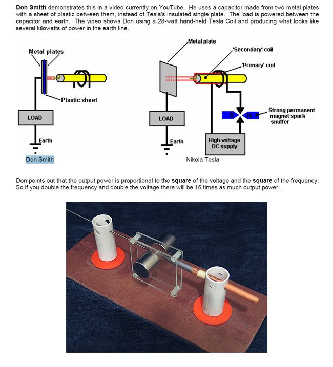
                    i am using two igntion coils in antiparallel, and can adjust things so that L1 oscillates at 14khz to 50khz,

                    Then with a 1/4 relationship, L2 will copy L1.

                    "You dont have to know about tuning to do this" --Don
                    In the beginner's mind, there are many possibilities.
                    In the expert's mind there are few.
                    -Shunryu Suzuki

                    Comment


                    • Originally posted by soundiceuk View Post
                      Is that the whole of your primary and secondary weight the same or your primary and one half of your secondary weight the same?
                      1.
                      I understand Tesla that the copper weight is an issue for getting optimized results. So my notion is that the first approach should be an easy one - to relate total primary to total secondary. Further tuning can be postponed if we have a working device. This property is not an essential one like wire length or resonance (my notion).

                      2.
                      Another essential issue seems to be (my notion) having copper cross-section related to the amout of current in secondary. The issue seems not to be the Ohms's resinstance but the aibility of copper to receive energy (copper mass). If this is true then it will not help using copper tube (skin effect) - then it should be massive copper alternatively the copper mass of tube corresponds to the current requirements. First level issue: copper mass / second level issue: deal with skin effect

                      3.
                      @ALL: Question regarding length:
                      If we have CW/CCW coil: Does the ratio 1:4 relate to both cw/ccw added or to one half only?
                      Last edited by JohnStone; 01-26-2012, 08:17 AM.
                      Experts spend hours a day in order to question their doing while others stopped thinking feeling they were professionals.

                      Comment


                      • 3.
                        @ALL: Question regarding length:
                        If we have CW/CCW coil: Does the ratio 1:4 relate to both cw/ccw added or to one half only?[/QUOTE]


                        I Think you are looking for this, like me.
                        Attached Files

                        Comment


                        • Originally posted by joefr View Post
                          ...
                          I will explain all combinations I tried today:
                          B=bulb C=capacitor (3.3uF) _ _ CW _ _CCW coil

                          1. B_ _B_ _ Bulb is lit but not full brightness
                          2. B_ __ _B Bulb is not lit
                          3. B_C_B_ _ Bulb is lit full brightness
                          4. B_C__ _B Bulb is lit half brightness
                          5. _C_B_ _B Bulb is lit full brightness
                          6. B_C__C_B Bulb is not lit
                          GREAT!
                          Case 5 is what Utkin describes.

                          Please take in account that the bulb will take about 4A at 14V. The wire diameter is ok for Ohm's law. BUT:
                          @ALL: Does anybody know if we need more copper mass in secondary in order to harves 4 amps?
                          Experts spend hours a day in order to question their doing while others stopped thinking feeling they were professionals.

                          Comment


                          • Originally posted by editor View Post
                            3.
                            @ALL: Question regarding length:
                            If we have CW/CCW coil: Does the ratio 1:4 relate to both cw/ccw added or to one half only?

                            I Think you are looking for this, like me.[/QUOTE]
                            Yes well! THANKS!!!!!!!!
                            Experts spend hours a day in order to question their doing while others stopped thinking feeling they were professionals.

                            Comment


                            • Originally posted by soundiceuk View Post
                              Here is an interesting video and Roberto's channel, if you haven't seen it before:

                              HorizonDelta's Channel - YouTube


                              I have a couple of his writings that used to be available on his website if anyone can host them.

                              I'm sure that there is some very valuable information there.
                              Have Pm'd you regarding ..
                              Whatever you can do,or dream you can,begin it.Boldness has genius,power and magic in it.Begin it now.

                              Comment


                              • If anyone’s HT trigger and coil can reach the frequency may I suggest trying to feed L1 at the second resonant frequency .. the linear resonant frequency as described http://www.deltaavalon.com/immagini/...%20version.pdf
                                and in the pdf by me in a more rambling way as you can see it should be F1 x 1.57 approx into the same circuit ..and it could well produce some interesting results! I have two reasons to suggest this.

                                1/ You probably recall ZZZZs post where she said the high frequency supply should be pulsing DC ? If you watched this video Coil Resonance Tutorial 1 - YouTube you probably recall that regardless of wave shape at Hertzian resonance a sine wave is produced .. that begs the question why would ZZZZ care less what sort of wave shape the HT produced ? Perhaps because its resonant to the linear wave???? It would certainly make a hell of a difference then! Its certainly got to be worth a little time to investigate dont you think ?

                                2/ I sort of visualise the linear wave as a wave pulled tight almost as a solid bar as far as feeding power in to it goes, everything you try to push in is 100 % reflected back. and the same force is applied at the other end, now imagine this tight stretched wave being “Twanged” by the action of the spark gap.
                                Of course if you tried doing this with a radio transmitter the reflected power would probably blow up the output stage .. but you haven’t got a radio transmitter.
                                This is how I view the power transfer described by Tesla in his own words here http://dnp.s3.amazonaws.com/b/b2/312...e-Wireless.pdf
                                Last edited by Duncan; 01-26-2012, 09:51 AM.
                                Whatever you can do,or dream you can,begin it.Boldness has genius,power and magic in it.Begin it now.

                                Comment

                                Working...
                                X