Announcement

Collapse
No announcement yet.

Donald Smith Devices too good to be true

Collapse
X
 
  • Filter
  • Time
  • Show
Clear All
new posts

  • Originally posted by Farmhand View Post
    People can be deceiving too. And looks can tell truths as well.

    The onus is not on the ones who cast doubt, to disprove what is claimed by others.
    The onus is on the ones who make claims to prove the claims they make.

    ..
    And where there is no Proof ?

    I have been to this thread before and gone away because I have seen claims I perceive to be invalid, but I have no wish to cause embarrassment by pointing them out in public.

    Yet many claims have been valid, though some are based upon various concensus understandings, not all of which we are presently educated in, and some of those understandings, which, though valid, could be 'poo-hooed' via present day 'theory' !

    Farmhand, I have watched the EVIDENCE of your investigative videos and the videos from others in this thread, and as you are concluding, there are none which have proven the development of over-unity.

    Closed circuits energised by electron activity CANNOT generate or 'pull' more electrons out of thin air, no matter whether tuned of length, or reactively resonant, or making sparks, or supposedly involving longitudinal radiation. End of ! Electrons do not exist in free air, only ions.

    The only 'free' (non-magnetic and non-mechanical) electricity I have seen recorded via a flow of electrons has been to neutralise positive ions, with those ions being related to atmospheric collection, radioactive decay, or an induced transmutation of matter.

    In the hope that I have not missed something whilst away, or whilst asleep and dreaming ...zzzz...
    I ask if anyone here has EVIDENCE to show that my knowledge is incomplete ?

    Your web veil hiding a glorious smile Zilano ?
    Last edited by GSM; 06-09-2012, 10:44 AM.

    Comment


    • Originally posted by soundiceuk View Post
      Very interesting progress in the Don Smith arena. Seems like word on the street is a number of members are coming forward with working systems.

      I'm sorry I never responded to the member who asked about Bruce's Radiant Energy Collection CD-ROM. The file was a compressed zip file in .exe format. Everyone who tried it had success.

      We are all here to free ourselves from slavery. I am here to help you all!!!

      Thanks to a very hard working bunch of like minded individuals here is the answer!!!!!!!!!

      - TEAM ION VALVE -


      Hi soundiceuk!

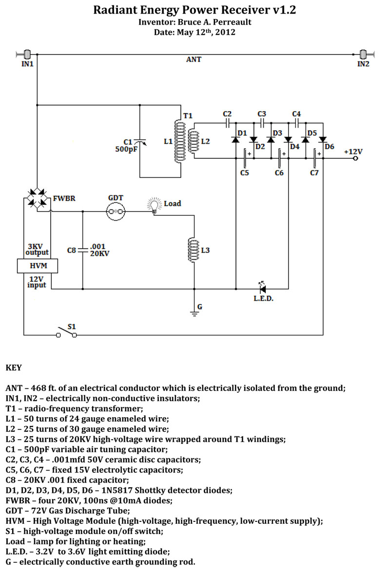
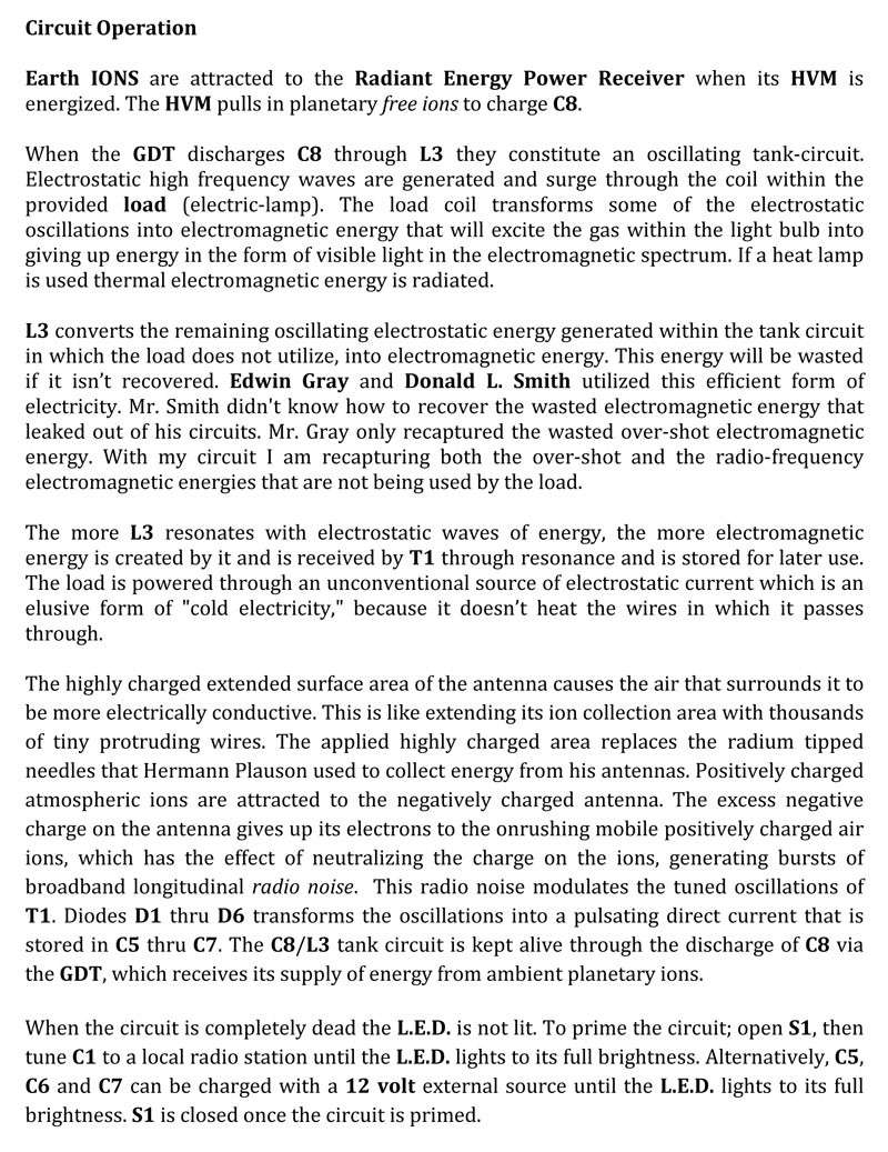
      I saw your posted circuit. i am very impressed and want to make it.

      would you kindly let me know what values of electrolytic capacitors C5, C6, C7 15 volts are.They are not specified in the schematic and the component list

      best regards

      xilo
      Last edited by xilo; 06-09-2012, 10:33 AM.

      Comment


      • Originally posted by Duncan View Post
        I'm not at all sure “doesn’t radiate any energy” would be the right term, perhaps doesn’t radiate any energy in a form we are currently familiar with might be a better turn of phrase. After all look at the shape and style of Tesla's antenna's


        do you know of any present day transmitter feeding a ball ? No of course not! Tesla was transmitting with a full standing wave. A system not taught and actively suppressed since the time of spark gap transmitters.
        Patent US1119732 - ELECTRICAL ENERGY - Google Patents
        The coil is 90 degrees to Earth ground.
        And the capacitor sphere is on extended wire tube end....

        Comment


        • Hi all
          this two tests of (half of thief circuit) and normal don smith circuit with homemade capacitor 4.5 nF >6000V
          aluminum foil and x-ray paper only two layer of x-ray paper and two layer of foil


          normal don smith circuit
          IMG_0080.JPG


          half of thief circuit
          IMG_0081.JPG

          test for half of thief circuit.jpg
          FREE ENERGY = FREEDOM
          raadawad[at]yahoo.com
          eng.raied[at]yahoo.com

          Comment


          • Originally posted by boguslaw View Post
            Guruji

            What is a power consumption of this circuit ? Does transistor get hot ?
            My ZVS consumes about 2amp measured with my MM. ZVS have two mosfets and runs cold maybe that's why this circuit is called Zero Voltage Switching ZVS.

            Originally posted by zilano View Post
            Hi Guruji!

            good work ! u r catching on. its like trying to learn a bicycle for the first time. U will get the hang of it. appreciate ur initiative and forwardness to experiment.

            keep safe high voltages are lethal. and can kill u. safety first experiment second.


            ....
            Thanks Zilano for your appreciation. Same to you I appreciate your openess to share your tech knowledge with us.


            Originally posted by blackrobi View Post
            Here, in this PDF the different positions of the spark gap and capacitor and what are the effects

            here is one case when the spark gap is before capacitor and on the bottom side of the circuit - Don Smith style

            http://www.energeticforum.com/attach...1&d=1339233023

            and here when the spark is between capacitor and the solenoid L1

            http://www.energeticforum.com/attach...1&d=1339232822

            rgds blackrobi

            [ATTACH]11382[/ATTACH]
            That's interesting Blackrobi. Does this mean that the last setup is best?
            Thanks for sharing

            Comment


            • GSM

              While tapping ions from air of electrons from ground (plenty because we are taught to spill all excess power to Earth ground) is interesting it is still secondary source of free energy. We are discussing pure Faraday's law induction method of tapping free energy . Energy is not in ions or electrons - it is in electric field difference flowing like a wave and performing work over electrons. Are we really convinced that electric power is converted into other forms like heat or light ???? What if not, if those are free except we are not recovering initial wave doing work. Hard to believe but I'm more and more convinced that Tom Bearden was right, except he didn't stated it clearly.
              What if we are wasting original electric energy and even paying for that waste ?!
              Last edited by boguslaw; 06-09-2012, 12:19 PM.

              Comment


              • Originally posted by blackrobi View Post
                Here, in this PDF the different positions of the spark gap and capacitor and what are the effects

                here is one case when the spark gap is before capacitor and on the bottom side of the circuit - Don Smith style

                http://www.energeticforum.com/attach...1&d=1339233023

                and here when the spark is between capacitor and the solenoid L1

                http://www.energeticforum.com/attach...1&d=1339232822

                rgds blackrobi

                [ATTACH]11382[/ATTACH]
                GOOD Work blackrobi

                excellent notes
                FREE ENERGY = FREEDOM
                raadawad[at]yahoo.com
                eng.raied[at]yahoo.com

                Comment


                • Originally posted by boguslaw View Post
                  GSM

                  We are discussing pure Faraday's law induction method of tapping free energy . Energy is not in ions or electrons - it is in electric field difference flowing like a wave and performing work over electrons.
                  Thanks for your reply Boguslaw.

                  Faraday's Law relates to closed circuits too, and is more commonly related to induced electromagnetic fields as are generated by charge (electron transfer) (energy) flow.

                  Where is this free energy, and where is evidence for it ?

                  Free space has a natural impedance, and can store/ return energy but it cannot return more energy than is induced into it in series with its own natural impedance.

                  Cheers ........ Graham.
                  Last edited by GSM; 06-09-2012, 12:58 PM.

                  Comment


                  • one more exp.

                    Hi Patrick , Hi All

                    Thanks for words

                    The voltage that I use is ~2500V it is for sure not more then that, the frequency I don’t know because I have a digital meter that has a frequency meter up to 200 KHz but if I put it around the device it is useless, it jumps from number to number .
                    But I think it is not greater then 25 KHz.

                    In meanwhile I tried this one

                    http://www.energeticforum.com/attach...1&d=1339261381

                    The field around the primary L1 is the weakest, but the spark on the secondary L2 became a strongest thou I can freely touch it no shock effect at all

                    The next thing that is in my mined is to put a capacitor before the spark gap in parallel and feeding it with AV plug.

                    rgds blackrobi
                    Attached Files

                    Comment


                    • a question

                      Thanks Zilano, Guruji, Eng. raied

                      I think the last one is the best, although I dont know should it bee in that way

                      The question is how could I post a picture that gonna be visible on the post

                      thanks blackrobi

                      Comment


                      • Sign up to a free account @ Image hosting, free photo sharing & video sharing at Photobucket

                        Upload your pictures.

                        Type the URL of the images location eg.

                        http://www.website.com/picture.jpg

                        All code on this forum starts with [] and finishes with [/]

                        For images it is [img] and [/img]

                        You must type this code before and after the image web address with no gaps to embed the picture in the post.

                        Comment


                        • next try

                          thanks soundiceuk

                          a try


                          Attached Files

                          Comment


                          • Originally posted by xilo View Post
                            Hi soundiceuk!

                            I saw your posted circuit. i am very impressed and want to make it.

                            would you kindly let me know what values of electrolytic capacitors C5, C6, C7 15 volts are.They are not specified in the schematic and the component list

                            best regards

                            xilo
                            GLAD TO HAVE CAUGHT YOUR INTEREST XILO

                            Latest schematic v1.3

                            http://f1.grp.yahoofs.com/v1/0EjTT20...ver%20v1.3.pdf

                            You can use 15v, 10,000uf to build a good proof of concept device.

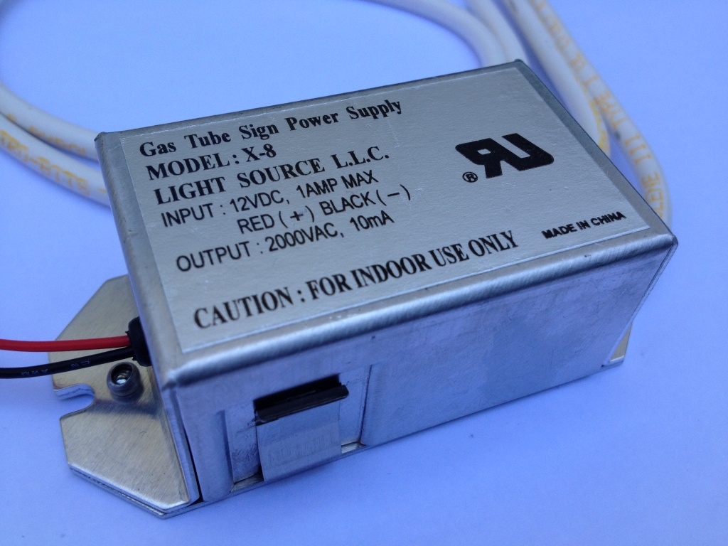
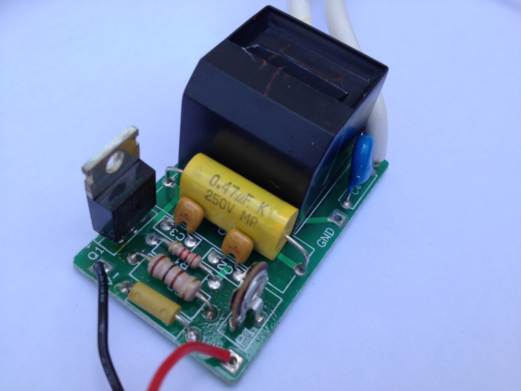
                            The reason the schematic changed is because of the new HVM.

                            Available from:

                            High Voltage, High Frequency Power Supplies

                            1 @ $19.95ea.

                            10-24 @ $14.95ea.

                            25-99 @ $13.95ea.

                            100+ @ $11.95ea.

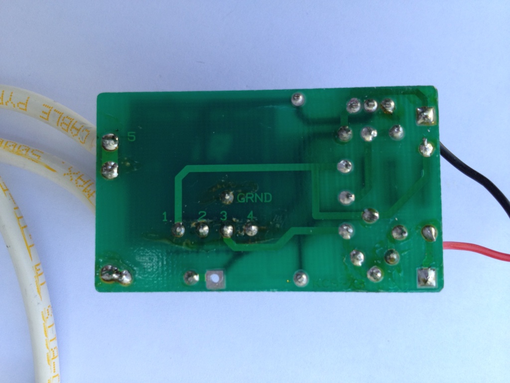
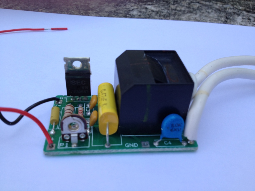
                            Here are just a few of the shots I took of the MiniMax3 Lenz kindly sent me, in raw format.


                            http://www.allelectronics.com/mas_assets/spec/HVS-1.pdf

                            http://www.nd.edu/~avorobie/projects...ce/minimax.pdf

                            Pretty Standard NPN BJT! These guys have been the work horse for so many experimenters.

                            The SEC version is a 70V / 10A / 75W BJT

                            MJE3055TG ON Semiconductor | MJE3055TGOS-ND | DigiKey

                            This will match it pretty well.

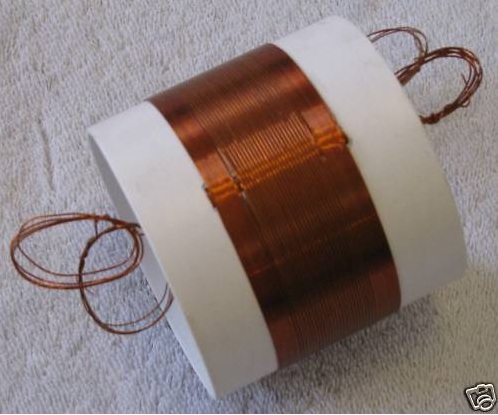
                            L1 & L2

                            Custom Wound Mystery Crystal Radio Coil


                            eBay - The UK's Online Marketplace

                            Want to know anything else pm me.

                            Comment


                            • Originally posted by blackrobi View Post
                              thanks soundiceuk

                              a try


                              You need to use the full name (quote this to see input text).

                              Comment


                              • Originally posted by blackrobi View Post
                                Thanks Zilano, Guruji, Eng. raied

                                I think the last one is the best, although I dont know should it bee in that way

                                The question is how could I post a picture that gonna be visible on the post

                                thanks blackrobi
                                when u upload the pic on this forum it shows as thumbnail in the post u posted. now go to ur own post and just right click on the thumb image of ur own post and select open in new window. another window will open and will show u the larger image of the pic u saw in thumbnail. again right click that big image and select copy and come to ur own post page and click edit it will open the edit window to edit ur post. now where ever u want to paste the picture in ur own posted text just right click and select paste and ur image gets pasted along with ur posted text.

                                its called inline embedding pictures. same way u can paste any image along with text. the same feature apply in emails too.

                                rgds

                                zzzz

                                Comment

                                Working...
                                X