Announcement

Collapse
No announcement yet.

Donald Smith Devices too good to be true

Collapse
X
 
  • Filter
  • Time
  • Show
Clear All
new posts

  • Originally posted by xee2 View Post
    This is not possible. If the two coils did not effect each other there would not be any energy coupled from primary to secondary. In all transformers the coils effect each other, that is how they work.
    maybe he meant that input current is not affected from open to loaded.... ?
    (just idling the primary)
    from the loose coupling, the back-emf from secondary not having a medium to propagate back thru? just guessing, but i notice no shift in input current while open, loaded, shorted. probably a good thing

    of course were learning, and im not sure if this applies, but Dollard did say that the Tesla waves were impulse waves, and i dont know enough to argue it, but that they are different from the conventional understanding.

    (but u prob know all this, you have excellent work)
    Last edited by mr.clean; 06-15-2012, 10:13 PM.
    In the beginner's mind, there are many possibilities.
    In the expert's mind there are few.
    -Shunryu Suzuki

    Comment


    • Originally posted by xee2 View Post
      This is not possible. If the two coils did not effect each other there would not be any energy coupled from primary to secondary. In all transformers the coils effect each other, that is how they work.
      Hi xee2,

      free energy is not captured by a transformer based setup. if it was than don smith, kapanadze, and sr193 must have used transformer at starting stage.

      and all radios i mean Am, Sw would have used transformer instead of ferrite cored coils.

      having a ferrite within a coil does help in raising L but it acts as free to air currents making north and south poles like a magnet

      i think its open magnet system where lines of force dont have to create flux in a metal they have to travel outside in the air to make a tornado and excite ambient.

      in transformers both primary and secondary effect each other thats why transformers are under unity systems. if transformers are made with primary not being effected by secondary then overunity can be achived but its not as much with single core that provides much more than a closed transformer core.


      I mean to say the coils are effected mutually by electrostatics not by closed flux loop induction as done in a transformer.

      when this electrostatic effect is used then secondary electrostatic effect must not effect primary.

      in short back emf of secondary must not effect primary.


      Thanks and regards

      dunfasto.
      Last edited by dunfasto; 06-15-2012, 10:01 PM.

      Comment


      • Originally posted by mr.clean View Post
        I keep wondering why you keep posting here then lol

        Of COURSE we all have doubts, but we are here building and trying to simply find out ways that it COULD work.

        The concept is very simple, resonance, if you are not experienced with it, does have a different behaviour.

        Resonant Energy Methods...
        POWER WHICH WOULD NOT HAVE OCCURED OTHERWISE.

        So now, I ASK YOU, how many radios can tune into the same radio station???
        Mr Clean, I am posting here to try to keep you from wasting your time.
        Is 2.5 years not long enough for someone here to have success with these 10+ year old designs ?

        Has Farmhand not tried very diligently and YouTube all of his findings ?
        Did you READ his post just before yours ?
        There are rewards on the net for OU designs because those who put up the challenge KNOW that their their money is safe.

        Yes Mr Clean - resonance is a most specific phenomenon, and you CANNOT draw energy from a resonant circuit without damping the resonance. Maybe you know of the maximum coupling for optimum resonance is 50% ?
        Resonance relies upon charge alternation, and the magnetic and coil voltage observations are at maximum 90 degrees either side of current flow.
        There is no free lunch just because of resonance, though induced resonance can be used as a power transducing arrangement from polarised sources.

        Donald Smith devices ARE too good to be true, and that is why I am here.

        How many radios can power a light bulb without needing power or 'fuel', so we need to find out what Don Smith really used !!!!!

        Comment


        • Originally posted by dunfasto View Post
          Hi xee2,

          free energy is not captured by a transformer based setup. if it was than don smith, kapanadze, and sr193 must have used transformer at starting stage.

          and all radios i mean Am, Sw would have used transformer instead of ferrite cored coils.

          having a ferrite within a coil does help in raising L but it acts as free to air currents making north and south poles like a magnet

          i think its open magnet system where lines of force dont have to create flux in a metal they have to travel outside in the air to make a tornado and excite ambient.

          in transformers both primary and secondary effect each other thats why transformers are under unity systems. if transformers are made with primary not being effected by secondary then overunity can be achived but its not as much with single core that provides much more than a closed transformer core.


          I mean to say the coils are effected mutually by electrostatics not by closed flux loop induction as done in a transformer.

          when this electrostatic effect is used then secondary electrostatic effect must not effect primary.

          in short back emf of secondary must not effect primary.


          Thanks and regards

          dunfasto.
          Well, I have never made an over unit device so I have no expertise on how they work. But I have made and used many transformers and I have never seen one where the coils did not effect each other. When statements are made that are inconsistent with experience, I think they should be viewed with at least a little bit of skepticism.
          Last edited by xee2; 06-15-2012, 10:26 PM.

          Comment


          • Originally posted by mr.clean View Post
            I keep wondering why you keep posting here then lol

            Of COURSE we all have doubts, but we are here building and trying to simply find out ways that it COULD work.

            The concept is very simple, resonance, if you are not experienced with it, does have a different behaviour.
            Sound waves fall under the frequency spectrum and can be analyzed the same way...

            Two singers at different notes, each at the same volume, (two frequencies, same wattage output)
            Now if the two freqs harmonize, you have a MEASURABLY higher decibel level than on separate notes.

            Now take solid object (for this example) if you give it a sharp pulse, it will resound at its frequency, LIKE A BELL. Probably inaudible, so lets take the well known...

            ...cup made of glass... It will have a ring... Now, simply match that ring and turn up the volume... The glass WILL break

            Now, you may notice that NO other freq, can do this other than the freq of ITSELF.
            The glass does not just break, it litterally begins to behave as a LIQUID, as it wobbles and comes apart unlike how a glass would NORMALLY break.

            You will also notice that it took a lower power level to do this than could be achieved with ANY other method.

            In electrical circuits, NO different, but not we use RF as our source, so now INAUDABLE, but the exact same process.

            When the LC on primary gets energized with a freq that it matches, it takes very low power to achieve maximum reaction on L2... For the least power... Primary resistance INCREASES, and the ring of TWO resonating secondaries, for the input needed to resonate the primary circuit only

            Don himself said that the ambient background was the source, and it it why lightning KEEPS happening, idk, how can anyone say they do KNOW, but it is also known that...

            THIS is WHY the EARTH SPINS, and YOU can simply calculate the weight of the earth, and the speed that it spins (1000mph)
            And the power needed to do that
            That is well known
            And didnt Tesla say on more than one occasion 10,000,000 horsepower?? Hehe

            Resonant Energy Methods...
            POWER WHICH WOULD NOT HAVE OCCURED OTHERWISE.

            So now, I ASK YOU, how many radios can tune into the same radio station???
            Mr Clean your car coils experiment is one of the BEST i seen on youtube in YEARS! You should pursue this some more like add high speed diodes etc and see how many watts can be extracted from the second coil versus driver coil.

            I am guessing you have a COP of around 3 or 4 but you need to validate this effect.

            Keep up the good work

            Comment


            • Originally posted by GSM View Post
              Mr Clean, I am posting here to try to keep you from wasting your time.
              Is 2.5 years not long enough for someone here to have success with these 10+ year old designs ?

              Has Farmhand not tried very diligently and YouTube all of his findings ?
              Did you READ his post just before yours ?
              There are rewards on the net for OU designs because those who put up the challenge KNOW that their their money is safe.

              Yes Mr Clean - resonance is a most specific phenomenon, and you CANNOT draw energy from a resonant circuit without damping the resonance. Maybe you know of the maximum coupling for optimum resonance is 50% ?
              Resonance relies upon charge alternation, and the magnetic and coil voltage observations are at maximum 90 degrees either side of current flow.
              There is no free lunch just because of resonance, though induced resonance can be used as a power transducing arrangement from polarised sources.

              Donald Smith devices ARE too good to be true, and that is why I am here.

              How many radios can power a light bulb without needing power or 'fuel', so we need to find out what Don Smith really used !!!!!
              Hi gsm,

              make a small circuit like Mr. woopy did and find out. Those who have tried they did not use opposite coils or caduceus.

              Please dont try to quash down the morale of the achiever.

              learn something here not criticize. its different physics here. you wont find in text books.

              make one and if it doesnt work then report failure else Dont babble.

              thanks and regards

              dunfasto

              Comment


              • Flyback specs?

                Originally posted by mr.clean View Post

                In the cap charging vid i was using a PVM500 at 70 khz, with 47uH caduceus L1 with a single .5" dia, 20 inch long rod to adjust inductance slightly, and .1uF 10kv cap for LC match at 70khz
                Hi Mr. Clean,

                What flyback were you using with the PVM500? Do you know the specs and core gap?

                Thanks!
                Duane
                Dude, you're curving my space-time.

                Comment


                • @ Xilo

                  Thanks for plugging the forum without any sort of prompt.


                  @ All

                  Sorry for my lack of communication.

                  Despite being able to enter your details on www. energy. team-talk. net

                  The forum is not freely accepting new members.

                  Bruce's 2nd Edition, which is nearing completion will feature schematic, videos and pictures of a multi-kilowatt device for purchasers to replicate. Anyone who has purchased a copy of the 1st Edition will be given a free upgrade.

                  If anyone would like to reserve a copy of the 2nd Edition. Firstly please contact me via pm.

                  Anyone who reserves a copy will receive a copy of the 1st Edition and given access to the forum within 24 hours.

                  This way, only the serious folks will be onboard.

                  As a bonus you will be receive Don Smith's Obtaining Energy from the Earth's Magnetic Flux 2 x DVD files & also Radiant Energy Collection CD-ROM files and help/support from our members to build your device.


                  @ Gedfire

                  My conclusion with Don's work is that it is not self sustaining. I'm not certain what happened to Dynatron but his videos looked the most promising for a break through. I would love to see a replication that is self sustaining.

                  I have 70% of the components to build Bruce's device. I intend to pursue his work, instead of Don's. I have a real soft spot for Don's work. We wouldn't be here without him!

                  @ GSM

                  The main reason I am doing what I am doing is because my research has shown me that we are all about to be heavily shafted by the greediest people on the planet

                  Have you watched Thrive?

                  Have you watched Thrive Exposed?


                  @ All

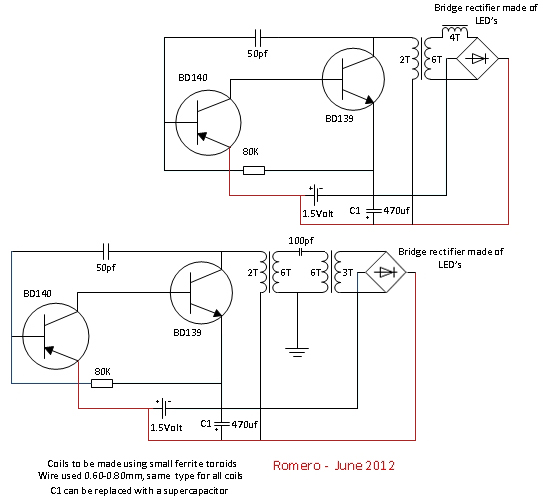
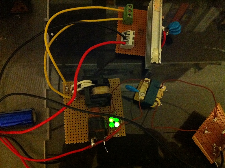
                  Here is a very interesting circuit for you to look at by one of the world's greatest electronics wizards!!!

                  It has been running for over 3 weeks now without the battery, after initial capacitor charging.


                  Comment


                  • Neat circuit Soundiceuk.

                    Maybe it should get its own thread here.
                    So why does it keep running - Leds are different beasties and more efficient at HF - maybe they are regenerating some energy via their bridge connection ?

                    Comment


                    • Originally posted by SilverToGold View Post
                      William Lyne posted this in regards to his device discussed in his "Free Energy Surprise" booklet.

                      The only person I know of who has obtained useful energy from this device was a man (now deceased) named Don Smith who added a resonant inductor tuned to 60 cps to the device and ran a Coke machine with it, using only battery power through an inverter to 120 volts A.C.. Don had called me earlier for a discussion and I suggested adding the inductor and he did it. He and his group (retired CIA investors) tried to interest a Japanese group in the device and they came for a demonstration years ago. They were
                      expecting a multi-million dollar contract. But they had copies of my books laying around the workshop so the Japanese group discreetly obtained my phone number and address from those. One book had over 60 references marked.

                      The Japanese group returned to Japan and sent a check to Don for $5,000 just for the demonstration, but did not sign the big contract which Don's group expected. Then the head of the Japanese group called me and ordered a copy of FES, paying handsomely. Don then said the group was "the Yakuza", a comment which I think was just sour grapes.I built one with an inductor but never completed any tests for lack of time or energy to devote to the project. I don't have the radio expertise or equipment which Don had. My main thrust is with the Lyne Atomic Hydrogen Furnace.

                      Bill Lyne


                      For more info on this device, go to:

                      freeenergysurprise : Free Energy Surprise
                      Hey There SilverToGold

                      I read your post on the FreeEnergySuprise Device. And I'm here to tell you it is for real I have built one.

                      I used a Gas Tube Sign Power Supply By LIGHT SOURCE LLC at 2000 Volts @ 10 ma amplified with a 15000 volt Multiplier

                      And put a Amp Meter on it and it showed 1 amp when the battery was fresh and then dropped to .5 amp

                      According to the Multiplier it showed put out about 17000 Voltd @ .0011765 amp but the amp meter says definutely .5 amp

                      But I don't believe the 17000 Volts @ .5 amp. anyway here a photo of my device.
                      Attached Files
                      Last edited by SLOW-N-EASY; 06-16-2012, 12:09 AM.

                      Comment


                      • Originally posted by Parav View Post
                        Hi Slow-N-Easy:

                        Thanks for your contributions on your experiments---they look very, very interesting to me and am surprised that not many people are jumping on it.

                        I have a couple of questions though, if you don't mind a little of your time.

                        Have you come up with a formula on obtaining the correct length of wire from the source battery to the NST to self charge that battery?? If so, can you elaborate on that please?

                        Is that 1st. circuit not as efficient as the 3rd. one ?? and have you actually have had all these circuits selfrunning???

                        Thanking you in advance for sharing this with us.

                        I tried to post a link but it did not work. If you have trouble finding maybe I can E-mail it to you

                        Paul
                        THe WEb site for the frequency of wire is CSGNework.com

                        THe program will calsc the length of the wire. Ihave not done extensive test of the charging rate but I am working on it

                        I will post more info as I learn and bild my devices. I haven't made one that will get me completely away from the grid

                        But I am very close. As far as the diferent builds they all have worked to some degree but I not completely there yet.

                        hope that helps in your quest.

                        Regards
                        Slow-N-Easy

                        P.S.The one that I like the best is the Nst running with a Voltage Divider and Inverter from a store it is very simple

                        way to get your onw power. Nothing to go wrong and everything has been tested by the manufactures
                        Last edited by SLOW-N-EASY; 06-16-2012, 01:07 AM.

                        Comment


                        • Ok, I was able to tune my custom nst from a range of 170khz to a little below 17khz using a cap bank array and a bunch of switches. I got tired of swapping caps on a breadboard. Yeah I know there is probably better ways to do it but it got the job done for me.


                          Using Don's silent spark gap configuration I went slowly from 170khz down to 17khz on my nst while my coils were set to resonate at 224khz. I got nothing.

                          I changed my coil set resonance down to 148khz and scanned again, nothing.
                          Maybe Don did purposely change the schematics. Although he did say when the device was running the lightning arrestor just glowed.

                          By nothing I mean I think a fly landed on my L2 coil while I was testing and it just sat there and stared at me.

                          Any suggestions?

                          Comment


                          • Originally posted by Parav View Post
                            THe WEb site for the frequency of wire is CSGNework.com

                            THe program will calsc the length of the wire. Ihave not done extensive test of the charging rate but I am working on it

                            I will post more info as I learn and bild my devices. I haven't made one that will get me completely away from the grid

                            But I am very close. As far as the diferent builds they all have worked to some degree but I not completely there yet.

                            hope that helps in your quest.

                            Regards
                            Slow-N-Easy

                            P.S.The one that I like the best is the Nst running with a Voltage Divider and Inverter from a store it is very simple

                            way to get your onw power. Nothing to go wrong and everything has been tested by the manufactures
                            On your question about why there has'nt been more people interest. I think most people don't think it can be so simple

                            And the truth is everyting in nature is simple keep it simple and you will succede. Follow Nature as much as you can.

                            And some people think it has to have alss these transitors and diodes and capacitors. Don always said that the reason

                            alot of the parts in a circuit are there because people think ythey should not that they are needed
                            Last edited by SLOW-N-EASY; 06-16-2012, 01:40 AM.

                            Comment


                            • Originally posted by SLOW-N-EASY View Post
                              P.S.The one that I like the best is the Nst running with a Voltage Divider and Inverter from a store it is very simple

                              way to get your onw power. Nothing to go wrong and everything has been tested by the manufactures
                              Which one is that?

                              Comment


                              • Originally posted by drak View Post
                                Which one is that?
                                Hey Drak I was referring to the first one I listed. It is a 9500 volt NST with a voltage divider and a store bought Inverter.

                                Everything there has been checked by the manufacture to be quality. A very simple device. The NST

                                puts out 285 Watts THat translates to about 23 amps @ 12v for the Inverter to run off of.

                                Regards

                                Comment

                                Working...
                                X