Announcement

Collapse
No announcement yet.

Donald Smith Devices too good to be true

Collapse
X
 
  • Filter
  • Time
  • Show
Clear All
new posts

  • Janost
    I'll give a quarter for the description on how this thing works... makes no sense to me.

    Larry

    Originally posted by janost View Post
    Try this one.
    It is a selfrunner but only when there is a real grounding rod attached.

    And I´m not even asking a penny for it

    [ATTACH]11799[/ATTACH]

    Comment


    • Originally posted by larryross View Post
      Janost
      I'll give a quarter for the description on how this thing works... makes no sense to me.

      Larry
      It is a stepup-stepdown converter.

      The first transformer generates about 800volt pulses into an Avramenko plug. It charges the 630nF cap using a single wire.

      When the gas discharge tube breakdown voltage, 200volt, is reached the cap discharges into stepdown transformer primary and transforms the voltage down and the current up on the secondary.

      The GDT rate is about 20Hz.

      The secondary is rectified and charges the 3,6v Li-Ion cell that feeds the supply voltage for the HV-blocking oscillator.

      It works without a grounding-rod but the battery eventually runs out.
      When it is grounded the glow from the GDT is stronger and the secondary of the stepdown generates a higher voltage with more current.

      The second AV-plug with the 5,6uF cap is a way to tap the circuit and use a load without disturbing the selffeeding loop.

      Comment


      • Thanks janost
        Interesting... I guess I haven't looked at enough of the self feeding circuits to keep from getting lost. I assume that the ground rod is the dipole which works better than just the open ended coil... has anyone tried an antenna instead of the ground? Why the 800 volts just to drive a 200V spark gap? The other thing that through me off is the SCR on a DC circuit.
        Is there a prototype or proof of concept or replications going on anywhere? What is the potential power output? Asking a lot of questions for a measly a quarter.

        Larry

        Originally posted by janost View Post
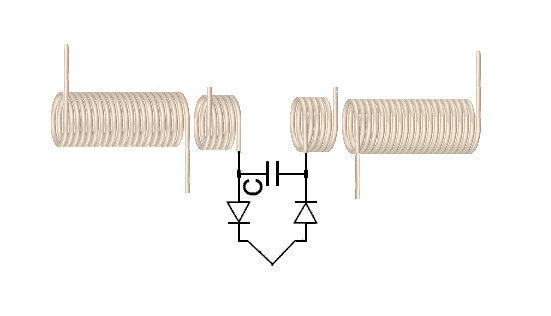
        It is a stepup-stepdown converter.

        The first transformer generates about 800volt pulses into an Avramenko plug. It charges the 630nF cap using a single wire.

        When the gas discharge tube breakdown voltage, 200volt, is reached the cap discharges into stepdown transformer primary and transforms the voltage down and the current up on the secondary.

        The GDT rate is about 20Hz.

        The secondary is rectified and charges the 3,6v Li-Ion cell that feeds the supply voltage for the HV-blocking oscillator.

        It works without a grounding-rod but the battery eventually runs out.
        When it is grounded the glow from the GDT is stronger and the secondary of the stepdown generates a higher voltage with more current.

        The second AV-plug with the 5,6uF cap is a way to tap the circuit and use a load without disturbing the selffeeding loop.
        Last edited by larryross; 07-22-2012, 08:44 PM.

        Comment


        • Originally posted by janost View Post
          It is a stepup-stepdown converter.

          The first transformer generates about 800volt pulses into an Avramenko plug. It charges the 630nF cap using a single wire.

          When the gas discharge tube breakdown voltage, 200volt, is reached the cap discharges into stepdown transformer primary and transforms the voltage down and the current up on the secondary.

          The GDT rate is about 20Hz.

          The secondary is rectified and charges the 3,6v Li-Ion cell that feeds the supply voltage for the HV-blocking oscillator.

          It works without a grounding-rod but the battery eventually runs out.
          When it is grounded the glow from the GDT is stronger and the secondary of the stepdown generates a higher voltage with more current.

          The second AV-plug with the 5,6uF cap is a way to tap the circuit and use a load without disturbing the selffeeding loop.
          hello Janost-& all

          I presuppose the 5k variable resistor controls the pump rate through the SCR and allows for a variable frequency to any load such as say a smith L1 primary coil? thanks and liked the info- mike,onward!

          Comment


          • The caps in the AV-plugs won't charge with a lower voltage.

            Yes, the 5K pot sets the pump rate through the load.
            The SCR fires when the gate voltage exceed 3volt and discharges the cap through the load.
            It's like a low voltage sparkgap.

            The secondary delivers 13volt and 400mA shorted.
            The blocking-oscillator draws about 70mA.

            It is selfrunning but only if it's grounded and I can't explain why.

            Comment


            • Originally posted by janost View Post
              It is a stepup-stepdown converter.

              The first transformer generates about 800volt pulses into an Avramenko plug. It charges the 630nF cap using a single wire.

              When the gas discharge tube breakdown voltage, 200volt, is reached the cap discharges into stepdown transformer primary and transforms the voltage down and the current up on the secondary.

              The GDT rate is about 20Hz.

              The secondary is rectified and charges the 3,6v Li-Ion cell that feeds the supply voltage for the HV-blocking oscillator.

              It works without a grounding-rod but the battery eventually runs out.
              When it is grounded the glow from the GDT is stronger and the secondary of the stepdown generates a higher voltage with more current.

              The second AV-plug with the 5,6uF cap is a way to tap the circuit and use a load without disturbing the selffeeding loop.
              Very good, I believe it can work. Next step is to run it on large capacitor and measure run time.

              Comment


              • Very well thinking, janost!
                Tell you later how it's working, I think needa fix (correct) the ground link.

                Comment


                • Move the circuit deep into forest where there is no AC power leakage to ground, just to be sure it's not powered by such currents. And use big precharged capacitor with zener diode protection to run circuit.If after 1 hour it will retain the same voltage level on capacitor it's definitely a kind of OU.

                  Comment


                  • @Janost did you wind your trany's or are they off shelf

                    I posted a coil configuration for Clarence

                    After thinking about it, actually I have been thinking on it for a long time, I dont think the current from the ccw coil can run with the current from a cw coil, the angle of propagation of the electrons running through the wire will not run with each other, they do in ac current but they are chopped into small segments.
                    Ed Leedskalnin said we didnt use positive electricity and I think this is what he was talking about cw has to run with cw it has its own pos(hole) and neg (elec)
                    Ccw has to run with ccw it has its own pos and neg as well.

                    When we change the magnetic field to an electric field we are splitting the poles, North makes its own monopole (electricity) and South makes its own monopole as well.
                    We are not spitting the pos and neg, we are splitting the poles, an thats where we get electricity (magnetricity)

                    The diagram I posted the two outer secondary's should be both cw.
                    The bucking coil is the anomaly we are looking for Boyd Bushman found that putting magnets in a bucking configuration had gravitational effects, there are more references to the bucking coil that I have run across in my research.
                    dave
                    Last edited by Dave45; 07-23-2012, 02:40 AM.
                    Half of the Answer is knowing the right Question

                    Comment


                    • possible schematic of your build?

                      Originally posted by mr.clean View Post
                      That being said... i got it to work with a regular AC nst, its not too hard,
                      You just cant touch the HV ends together like Dons,
                      I could explain it but here is a vid of mine with it...

                      https://www.youtube.com/watch?v=8FRB...hannel&list=UL

                      but yeah the PVM500 dominates all others ive tried, let me know if this vid helped, and make sure you let it load, or you miss the first BANG, even see if you can pause it on a discharge, theyre Big and like gunshots

                      ahh the vid doesnt show well, so

                      one of the HV from nst to a forward facing diode
                      the other HV to a back facing diode
                      parallel spark gap adjustable
                      from pos side to series tank cap
                      cap to series L1
                      L1 ending at the other spark gap side
                      L2 connections are the usual, go find out

                      now balance variac voltage, current draw, and spark distance with many hours of experiments, then post back with a vid
                      Hello Mr Clean, & all

                      in the attached thumb nail I came across a similar schematic of of dons chap #3 in patricks feng files. I modified it slightly according to everthing I saw when stop action scrolling you you tube video. I believe its very close. would you make any necessary comments please sir. thanks in advance, mike onward!
                      Last edited by clarence; 08-31-2012, 08:34 PM.

                      Comment


                      • Originally posted by janost View Post
                        The caps in the AV-plugs won't charge with a lower voltage.
                        Very interesting... how does a cap not charge???

                        Yes, the 5K pot sets the pump rate through the load.
                        The SCR fires when the gate voltage exceed 3volt and discharges the cap through the load.
                        It's like a low voltage sparkgap.

                        The secondary delivers 13volt and 400mA shorted.
                        The blocking-oscillator draws about 70mA.

                        It is selfrunning but only if it's grounded and I can't explain why.
                        Seems like a simple circuit might have to build to see how the impossible works.

                        Later
                        Larry

                        Comment


                        • The transformers are stock.
                          The stepup comes from a bugzapper and the stepdown is a 230v to 9v wallwart.

                          The GDT is just a flurocent-tube lighter with the supression cap cut out.
                          The exact breakdown voltage is 196v.

                          The GDT actually pulses the primary of the stepdown but on the secondary there is a ringdown happening with the transformers self-resonant frequency.
                          That is why I only half-rectified it instead of a bridge to keep the ringing.

                          I have burned out a couple of wallwart transformer running them with just a sparkgap before I figured out a GDT and the AV-plug performs excellent and the GDT fires before the primary winding breaks down.

                          The AV-plug does not put any strain on the stepup secondary as it charges passively.

                          I guess that the caps won't charge on a lower voltage because of leakage in the diodes.
                          We have 230v lines in my country and if connect the AV-plug to the livewire of a wallplug it only charges to about 6,5volts.
                          Last edited by janost; 07-23-2012, 09:37 AM.

                          Comment


                          • Originally posted by boguslaw View Post
                            Move the circuit deep into forest where there is no AC power leakage to ground, just to be sure it's not powered by such currents.
                            That is near impossible in the country of Sweden.

                            Have to be on an island in that case

                            Comment


                            • Hi Harish. I know about the distribution of fields in the coils of different shape and method of winding. I have no objection in this regard.


                              Hi, mr.clean
                              haha, this is funny,
                              are you saying that Tesla didnt use LC components?
                              I did not say that! I tried to express the thought of other ways of excitation of resonant systems
                              I only commented on the video DEDcolorado. In his design the use standing waves, of sinus-waveform, which are easily obtained using the quarterwave-line, such as in the picture.
                              I'm trying to say about another kind of standing waves.
                              Look at the picture of a powerful explosion, such as atomic.
                              What do you see? rightly - the mushroom cloud. What comes from the center of the explosion - it is the concentric a shock waves - this is the radiant of Tesla.
                              That is, the phenomenon we are trying to achieve in our experiments. You are nowhere in the books of Tesla did not find it, how to do it.
                              I hope I have given enough good comparison with the explosion.

                              P.S. I hope nobody thought I was going to teach someone else here. It is my opinion and the results of the experiments. I'm just trying to share my humble point of view, which does not claim to ultimate truth.

                              Regards to all
                              Vasiliy

                              Comment


                              • My circuit proves that you dont need real HV like ignition-coils or MOTs for this to work.

                                My theory is that it is actually the sparkgap and the ground-rod that does the magic.

                                Perhaps also the resonant ringing in the stepdown transformer.

                                Comment

                                Working...
                                X