 Tweet
Tweet
NOT TRYING TO BUTT IN _ Just a possible quick explanation
Hello Atta,
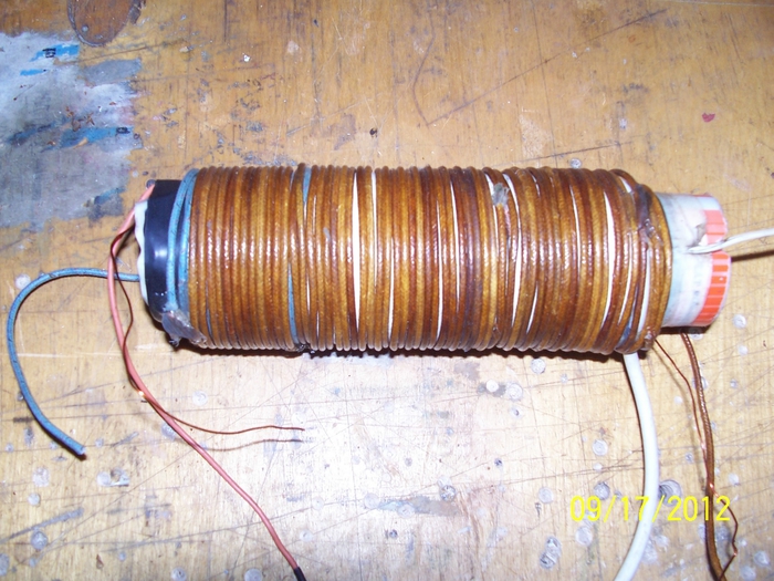
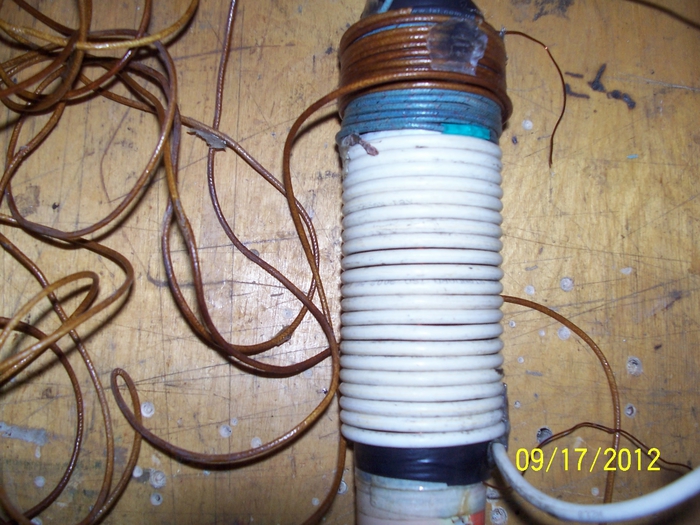
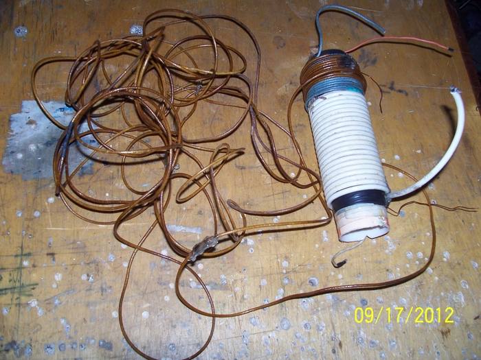
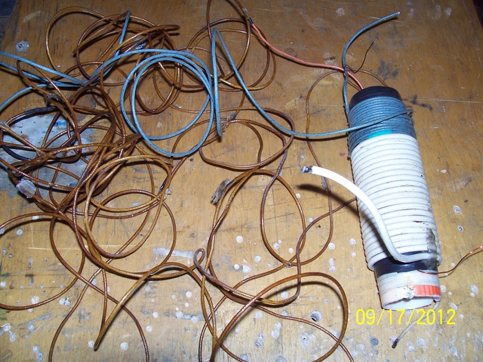
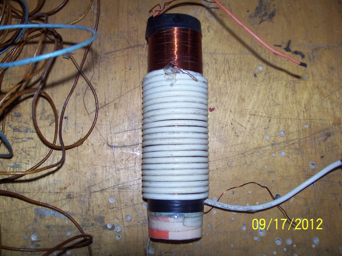
forgive me for seeming to but in, however I have a piece of info shown in the thumbnail that could be added for your benefit in addition to the info MR Clean provides. the component shown to ground the high voltage secondary could be what Don was referring to.
Mr clean,
not attempting to interferr with a quote addressed to you, definitely not my intention, just wanted to pass some seemingly direct information by an type component used to answer the question for a fellow member, thanks to all! mike onward!
Originally posted by atta
View Post
forgive me for seeming to but in, however I have a piece of info shown in the thumbnail that could be added for your benefit in addition to the info MR Clean provides. the component shown to ground the high voltage secondary could be what Don was referring to.
Mr clean,
not attempting to interferr with a quote addressed to you, definitely not my intention, just wanted to pass some seemingly direct information by an type component used to answer the question for a fellow member, thanks to all! mike onward!


Comment