If this is your first visit, be sure to
check out the FAQ by clicking the
link above. You may have to register
before you can post: click the register link above to proceed. To start viewing messages,
select the forum that you want to visit from the selection below.
Hello to all. I am going to try a duplication of some of Don Smith's devices so just wanted to say hello. I have started doing some basic experiments already at lower input voltages to try to get a better feel for how these circuits will behave at lower voltages, and am waiting for some parts to arrive before I can start into experiments at higher voltages. I will post here if I come across any interesting results.
The following is kind of long, but for anyone interested in the issues involved with making meaningful voltage and current measurements in AC circuits with complex waveforms, here is a little bit of info on it:Wish everyone good luck in their experiments...
that is awseome info man, great to know! yes definitely rectified and cap filtered, farmhand said that too
In the beginner's mind, there are many possibilities.
In the expert's mind there are few.
-Shunryu Suzuki
One more question. What space is the gap in the toroids? Are they split and then press backed together? In the video It almost looks like you glued them back together after you split them.
that is good info,i will try that. but i dont think i had it very stabilized with the battery when i did the video.
and one very interesting thing, was that if i connected the neg of cap to the neg side of load,m the cap would spike off the scale 5 amps negative, and slowly come to zero, and small cap shorting did not affect it, but it seems like once i used up all of whatever was making the meter dip negative, i couldnt do it again.
the toroids were scored, snapped in vice with rubber hammer , and only placed together and zip-tied, proper gapping in the right spots will prove harder than i thought
anyway, more to come
In the beginner's mind, there are many possibilities.
In the expert's mind there are few.
-Shunryu Suzuki
I've got a fair amount of Litz wire left over from a large spool I got for another project that I think I could use for doing the winds on the secondaries. Does anyone have any thoughts on whether that might be a good or bad idea? I don't want to assume it's better but if it would be as good I'd like to try using it as I don't have any single strand wire readily available for this project. I got the exact toroids mentioned here and will be working on cutting one in the next day or two.
There is no important work, there are only a series of moments to demonstrate your mastery and impeccability. Quote from Almine
I have done an enormous amount of research since last posting. This included direct conversations with Travis of the Travis effect, Tariel Kapanadze, the Magnacoaster scientific team and other succesful OU replicators.
My conclusion is that they are all using radiant energy albeit in different formats.
The points to remember are that the circuit has to be switched on and off rapidly.
The on time has to be less than 1 millisecond.
This effect of itself generates high voltage spikes, which is the sign of radiant energy. The frequency time has to be as high as possble - into the mhz if possible.
The reason spark gaps sometimes work is that this condition can be recreated at resonance, however it is more likely to be miss than hit.
Better to use a digital gating system.
Resonance between L1 and L2 can be automatically induced by both coils sharing negative ground. This also prevents a floating voltage from putting the build out of phase.
We shouldn't be surprised.
All this info on radiant energy is in Tesla's talks and patents.
Somewhere between post #7779 and post #7829 we lost a 10K Ohm resistor that was originally (R7) and was just to the left of the toroids in series with a 100nf cap. Those two components were in parallel with the input to the primary of the toroids. mr. clean or verpies or anyone - can you confirm it was removed for a reason or did it just get accidentally left out on verpies revision? It was shown in verpies original diagrams like in post #7779.
I'll take a guess at answering my own question. mr. clean did not have a resistor in his hand drawn diagram posted after verpies had made the early diagram. So now I'm just double checking to make sure it is correct that there is NO 10K Ohm resistor in that position.
I have done an enormous amount of research since last posting. This included direct conversations with Travis of the Travis effect, Tariel Kapanadze, the Magnacoaster scientific team and other succesful OU replicators.
My conclusion is that they are all using radiant energy albeit in different formats.
The points to remember are that the circuit has to be switched on and off rapidly.
The on time has to be less than 1 millisecond.
This effect of itself generates high voltage spikes, which is the sign of radiant energy. The frequency time has to be as high as possble - into the mhz if possible.
The reason spark gaps sometimes work is that this condition can be recreated at resonance, however it is more likely to be miss than hit.
Better to use a digital gating system.
Resonance between L1 and L2 can be automatically induced by both coils sharing negative ground. This also prevents a floating voltage from putting the build out of phase.
We shouldn't be surprised.
All this info on radiant energy is in Tesla's talks and patents.
Who here didn't know about needing high pics at high frequency in such Device?!
But for the commun ground, yes, could be a detail which makes a difference.
Trying to understand perfectly something, observing by one's self to check the truth, is the only way to skills and to protect oneself from false data and rumors.
Aye, just wanted to mention it mainly for some people who may be just starting out and not too familiar with that sort of thing yet. Hopefully it will be of some use to some people. I hope people will be very careful with these circuits as well because obviously high voltage can kill, and a capacitor charged to a high voltage can kill instantly if the capacitor lead is accidentally touched. These can be quite dangerous circuits if a lot of care is not taken when working on these circuits live.
really do appreciate your last big post, i will need to look at that a few more times no doubt
Iv been thinking about the TPU and the Bitoroid I think they have alot in common and I think the bitoroid design would stop the heating problems SM had.
I was thinking this morning about the story SM told of the TV imploding and I think he took that seriously and investigated it very well, it was the choke and Sm thought so too, thats why he started working with the toroid.
What does the choke do, stops RF from entering the circuit the aether is collected at the choke
How is a choke wound, cw and ccw windings
I think the TV implosion was the result of the flyback shorting to the choke.
I also noticed SM used single windings, single directional windings
We are working in the right direction and will lead to free energy, keep plugging along
later
dave
I think when its found it will be a combination of Leedskalnin's PMH, SM's TPU and Thain's Bitoroid.
'
I agree and that's what I said briefly a couple pages back that there are similarities here with mr. cleans bitoroid and the TPU. I look forward to playing around with this. I just took a brief try last night at scoring the toroid to split it. That is some seriously hard stuff. I was using a large floor model metal band saw that I use for cutting titanium and stainless steel. It took quite a while to just get a small score in this toroid.
I'm not sure now how to tackle splitting this toroid as I see now Digikey is sold out of them and I'd hate to break it in the wrong way. I'm thinking a metal cutoff wheel on a grinder might get through it. I've got Dremel stuff but seems like it would eat dozens of wheels to get through it or even a good size score. Will these tend to break clean with a small score?
There is no important work, there are only a series of moments to demonstrate your mastery and impeccability. Quote from Almine
I havent tried it but I'd bet a wetsaw used in the ceramic tile business would cut the ferrite, it uses a diamond blade cooled by water, the water also keeps the material cool.
I believe my brother has one, will give it a shot and report back.
later
dave
I agree and that's what I said briefly a couple pages back that there are similarities here with mr. cleans bitoroid and the TPU. I look forward to playing around with this. I just took a brief try last night at scoring the toroid to split it. That is some seriously hard stuff. I was using a large floor model metal band saw that I use for cutting titanium and stainless steel. It took quite a while to just get a small score in this toroid.
I'm not sure now how to tackle splitting this toroid as I see now Digikey is sold out of them and I'd hate to break it in the wrong way. I'm thinking a metal cutoff wheel on a grinder might get through it. I've got Dremel stuff but seems like it would eat dozens of wheels to get through it or even a good size score. Will these tend to break clean with a small score?
I f i may suggest in case you cannot cut it ... a while back i stumbled on this vid :
Demonstration of making magneitite cores. Robert Adams and others have claimed magnitite cores made thier motors more efficient. I am not claiming that yet for I havnt done any tests to prove that yet, however i can tell you that they seem to make a weaker electromagnet and are less attracted by magnets that than typical silicon-steel cores. Im going to try and update this as i make new findings.
1/30/2009
The lindemann attraction rotor i was working on is not going to work with magnetite. The coils magnetic field is to weak for that. It also preformed poorly with my magnet rotor until i discovered something. I was using weak ceramic magnets, the type bedini suggests. They attract very little and repel very little to magnetite. However, i tried some strong neodymium magnets and it preformed very well. Neo magnets on the rotor are the way to go with magnetite.
�Signs and symbols rule the world, not words nor laws.� -Confucius.
To separate the toroid nicely into halves we need to 'etch' a cut line around the core (with a glass cutting tool or dremel), heat that part of the core up and rapidly cool it down, similar to 'wine bottle cutting trick' It should crack evenly as it is of a ceramic nature
hi people, little update, im experimenting with different capacitance and things, even tried to make another bitoroid with flybacks you see here, and some interesting things to come.
im going to return to the self-looped circuits after im satisfied its at its peak performance, it just keeps getting better so im looking to see what hidden potential awaits.
the current in and out are very exciting here.
i arrived with this setting by shorting output to induce max response on output ammeter, while simultaneously watching for the lowest input current reading as i adjusted and balanced freq and duty cycle.
And no the 9v cant run anything but the base, when pos on battery comes off, it shuts off, anyway..
these numbers basically crudely show that even on operating load, the output current exeeds input, and output current dramatically climbs under short-circuit, its just hard to find a load with low enough resistance to get output current up LOL
its prob safe to say also the secondaries also have a higher voltage that primary
call that what you will
 Tweet
Tweet


 the aether is collected at the choke
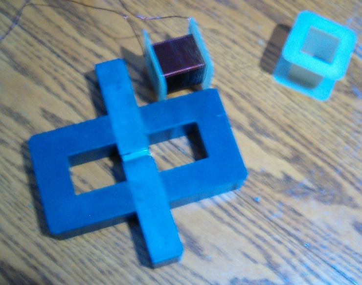


Comment