If this is your first visit, be sure to
check out the FAQ by clicking the
link above. You may have to register
before you can post: click the register link above to proceed. To start viewing messages,
select the forum that you want to visit from the selection below.
I really see no reason to use a scope to measure power between a battery and a capacitor. Maybe to check for a voltage fluctuation on the cap?
If the input voltage and current to the DUT are constant then a scope is not necessary and simple multimeter will suffice. Are they constant? The answer is not obvious just because an input capacitor is used (RC time constants, ESR, inductance, etc...)
...and what about output power measurement? is it DC?
That is an interesting question. How much DC power does it take to light an AC LED bulb to the same brightness.
LEDs are inherently DC devices. AC doesn't make much difference because the current supplying the LED Bulb is rectified and integrated anyway before it reaches the LEDs.
Hi all, We do pay for the losses involved in the the supply of the power at the
socket when we pay our bills, anything other than what the socket provides as in
frequency ect. will incur more losses, such as the signal generator.
Anyway without considering the signal generator power I would setup the
measurement like in the drawing. Mr Clean can you modify the drawing to show
where you take the measurements with the LED to get the input power
measurement ?
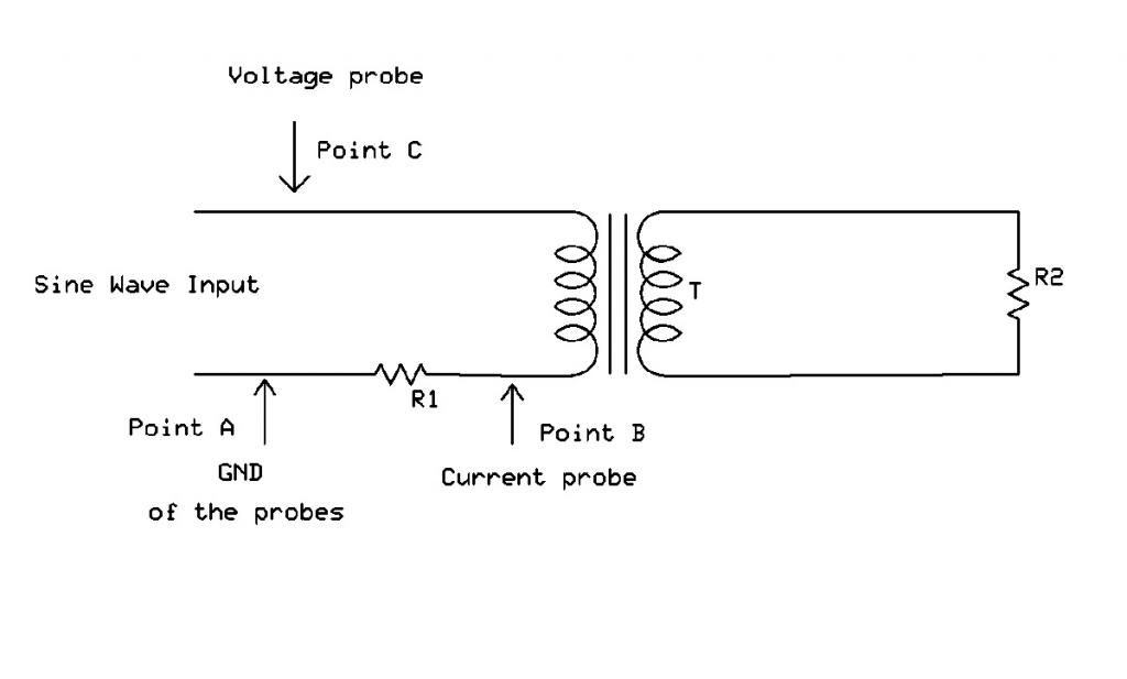
I would measure the RMS voltage across R1 at points (A) and (B) in volts then
divide it by the resistance in Ohms to get the current through the primary,
then multiply the current by the RMS voltage measured at points (A) and (C) to get the apparent power.
Then there is the power factor which could only help. Anything less than 1.00
will mean the real input power is less. Still with such low power levels the
chance of measurement error is high in my opinion. If you do away with LED's
and size the resistors properly you can go up in power and see more accurate
results.
Cheers
i have a question about the measuring points
on the secondary, the V across resistor is comparable to the primary resistor in series?
the resistor on secondary seems like how the current was read in primary.
this may sound dumb, but is V to be read open wires?
or how else to measure than across resistor?
there is only one measuring point on secondary?
In the beginner's mind, there are many possibilities.
In the expert's mind there are few.
-Shunryu Suzuki
on the secondary, the V across resistor is comparable to the primary resistor in series?
the resistor on secondary seems like how the current was read in primary.
this may sound dumb, but is V to be read open wires?
or how else to measure than across resistor?
there is only one measuring point on secondary?
Hi mr.clean,
Quick answers
on first question: no, not really comparable. The series resistor, R1 (non-wire wound) is usually 0.1 or max 1 Ohm (depends on how high the current) NOT to influence the actual current flow but still give enough info with the voltage across it what you actually measure and calculate current.
The resistor across the secondary (R2) is a load resistor, its value can be anything from 10 to 1000 Ohm or whatever, depends on the actual output power, should be non-wire wound also. Its wattage rating should correspond to the output power expected: say you get 3 Watt useful power output then you may wish to use at least a 5 W or even higher wattage power resistor not to overheat it in the first seconds.
second question: V should not be read open wires, it is meaningless in most cases. IT should be measured across the connected load.
third question: there are two connection points on secondary they are the coil ends of course and when the load is also hooked up you can measure across the load legs.
Gyula
Last edited by gyula; 11-25-2012, 11:46 PM.
Reason: more clarity
If the input voltage and current to the DUT are constant then a scope is not necessary and simple multimeter will suffice. Are they constant?
They are constant and I see no reason to use a scope unless I was checking for voltage fluctuation on the cap.
LEDs are inherently DC devices. AC doesn't make much difference because the current supplying the LED Bulb is rectified and integrated anyway before it reaches the LEDs.
Since you asked I decided to check. The bulb starts to just glow at around 45v DC. At 70V DC pulling 50uA the bulb is almost as bright as it is running on the CrossOver circuit using 15V DC at 50uA.
on first question: no, not really comparable. The series resistor, R1 (non-wire wound) is usually 0.1 or max 1 Ohm (depends on how high the current) NOT to influence the actual current flow but still give enough info with the voltage across it what you actually measure and calculate current.
The resistor across the secondary (R2) is a load resistor, its value can be anything from 10 to 1000 Ohm or whatever, depends on the actual output power, should be non-wire wound also. Its wattage rating should correspond to the output power expected: say you get 3 Watt useful power output then you may wish to use at least a 5 W or even higher wattage power resistor not to overheat it in the first seconds.
second question: V should not be read open wires, it is meaningless in most cases. IT should be measured across the connected load.
third question: there are two connection points on secondary they are the coil ends of course and when the load is also hooked up you can measure across the load legs.
Gyula
ok i think i have some readings
primary across leads:
2.04v open wires
1.97v connected with secondary load
1.90v open secondary
primary across 1 ohm in-line resistor:
.020v
secondary reading across leads:
9.28v
reading 10 ohm resistor .563v
does this mean anything?
i could get it better i think with some properly done windings lol
plus i may not be doing this right, do these readings make sense or should i do a vid?
From the measurements here is what can be figured out, ASSUMING your voltage values are RMS and ASSUMING that the voltage drop (0.020V) across the 1 Ohm (R1) resistor is measured when the 10 Ohm (R2) resistor is also connected to the secondary, ok?
input power to the primary 1.97V*0.02A=0.394W (the primary current 0.02A comes from the 0.02V drop divided by 1 Ohm)
output power dissipated in the 10 Ohm load (0.563*0.563)/10=0.031W (from formula (V*V)/R)
I cannot understand this voltage:
1.90v open secondary when you have also this: 1.97v connected with secondary load
EDIT: I also assumed that the primary current is in phase with the primary voltage, this can only be read from scope, if there is phase shift then the power 0.394W should be multiplied by the cosine value of the phase angle. Sorry for not mentioning this earlier.
Although i agree on useing a 1ohm resistor in series to the primary coil to measure input current,i think useing low ohm resistors on the output inductors is not the way to go to measure output current.
An inductors resistance will climb with voltage,some times (depending on voltage and configuration)up into the kohms.
Now if you go and place a 10 ohm resistor accross that inductor,the resistance in that inductor can never climb higher than 10 ohm's-infact less.
This now then changes the carictoristics of that inductor,and how it perform's.
It would make more sence to use a high ohm value resistors(say 10k) on the output inductor,so as the resistance can rise with the primary.
The other way to measure watts in to watts out is timed run,s(say of a minute)and have the output current charging a cap.
For minimal losses you could use two caps in a voltage doubler configuration,so as only the loss of two diodes is encountered for a smooth dc output.
We then can calculate the joules of energy in those two cap,s after the 1 minute run.
This can then be calculated to watt second's,as can the input.
The good thing about electrolitic caps is that although there series resistance is very low,the parallel resistance is very high(some in the meg ohm range).
And when used in a voltage doubler configuration,that resistance is doubled.
This will allow the secondary inductors(coils)resistance to rise,and not be limited by the value of the load resistor.
They say that electrical circuits can be seen as watter in pipe's.
So there is no point in haveing a two inch pipe if your going to put a 1/2 in valve on it,and then try to calculate how much water that two inch pipe can deliver under a set preasure
very interesting, so use higher ohms on output?
yes good ideas. but what is the reason? this not adequate to get info?
idk,but i'll make a vid of what i did to check the figures i mentioned, and tell me if its correct....?
Hi mr clean. You don't need to measure any open circuit voltages (open wires) to measure the power out and power in. You just need to hook up your circuit and make your RMS voltage measurements using your scope probe with everything connected up and running as normal, with the exception that you are placing a 1 ohm resistor in series in the primary. See my diagram posted previously on exactly where you would need to make your RMS voltage measurements. In other words, all the RMS voltage measurements are done with the circuit running, and without making any changes of any kind to the circuit, and without disconnecting any wires or components in the circuit while you make all the required RMS voltage measurements. So, with everything connected up in the circuit (including the 1 ohm series resistor in the primary) and the circuit running, you just move the scope probe ground lead connection and scope probe tip connection to the points indicated in my diagram. For each red arrow indicated in my diagram, the bottom of the red arrow would be where you connect your scope probe ground lead connection, and the top of the red arrow (the arrow point) would be where you connect the tip connection of the scope probe. Do this for each red arrow indicated in my diagram.
You would also need to indicate whether you had a load resistor connected to each secondary winding, or if you only have a load resistor across one secondary winding and have a short placed across the other secondary winding. If you have a load resistor across each secondary winding, you will need to measure Vrms across both load resistors and indicate what the resistance value is for the one or two load resistors you are using.
With only a single probe scope, you will need to take all of the RMS voltage measurements I indicated in my diagram in order to calculate real power in and power out. The two voltage measurements on the primary that farmhand indicated would not be enough to measure the real power input to the transformer. Real input power measurement using a single scope probe will require the three voltage measurements on the primary which I indicated in my diagram. Even then, if your input waveform to the transformer primary is not a very clean and undistorted sinewave, the numbers will not come out right. If it is only a little distortion on the sinewave then the numbers may still come out close enough to get an overall idea what your circuit is doing. I did some tests with my transformer using a somewhat distorted sinewave (I had glitches on the input sinewave waveform plus distortion) and the numbers did not agree very well at all when I compared the results of measuring the transformer input power and power factor using two different measurement methods to double check the results.
hmm no wierd glitches here, but who knows at this point...
Hi mr clean, Watched your video. You are definitely on the right track, but still a few changes required yet. You won't need to measure any open circuit voltages in your circuit, but there are three RMS voltage readings needed on the primary side (using my single probe power measurement method anyway). See my previous post to you which you just replied to with the details on this. Also, a couple of things that will help to make your measurements more accurate are:
1) I noticed that in your scope settings your scope probe setting is set to x1. If your scope probe has a switch on it for x1 and x10, set the scope probe switch setting to x10 on the scope probe, and then go into the scope settings menu also set the scope probe setting in the scope menu to x10 as well, to match the new switch setting on the scope probe. Setting the probe to x10 gives the scope probe a higher input impedance, and with a higher input impedance the scope probe will load your circuit down less when making measurements, so the voltage readings will be more accurate.
2) When measureing a voltage waveform with the scope, try to set your scope so that the waveform fills as much of the scope screen as possible without the top and bottom of the waveform touching the top or bottom line on the scope. The scope may read the voltages a bit more accurately this way.
I did notice that your input sinewave is a little bit distorted on the primary when under load, but that may be unavoidable as the primary puts a fair bit of load on the sinewave generator, and this will often distort the waveform of a generator a bit.
By the way, I believe you are using a 10 ohm resistor on one of the secondaries. What do you have connected to the other secondary? Do you have a short across the other secondary winding?
the secondaries are in parallel, but unhooked one to get inside the circuit for the final voltage reading.
otherwise they are both engaged to the same resistor.
doesnt this give some sort of calculable figure?
I did already watch your video # 41, ant that was what I was responding to in my last post to you. You would need to take the three primary side voltage measurements exactly as indicated by the red arrows in my diagram for the power measurement method I was suggesting. See my last couple of posts for specific details. On the secondary side of your transformer, you can either hook your two seondaries in parallel across the single 10 ohm load resistor (not sure what overall effect that will have, whether good or bad), or you can just connect the 10 ohm resistor to one of the secondaries and place a short across the other secondary. Shorting one of the secondaries appears to be how Thane Heins was doing his power measurements from what I can gather anyway, and when I did this in my tests it gave me maximum power to the load resistor on the other secondary.
thats what im saying, the 2 sec are together in the vid the whole time except for the final v reading 9.28v.
Also Thane always had the coil resistance and a load resistances notated, not shorted.
both were added up separately, but i see more than a perfect doubling when i parallel them, so i think this is best.
cant we at least (from my last vid) go roughly by:
input
1.97v @ 20ma
(20mv across 1 ohm)
----39.4mW
output
9.28v @ 56.3ma
(563mv across 10 ohm)
----522mW
?
In the beginner's mind, there are many possibilities.
In the expert's mind there are few.
-Shunryu Suzuki
I agree with Gyula calculation. Since the circuit is actually an LC tank in parallel resonance and you adjusted to resonant frequency, I don't think we have to worry about phase too much. The calculation did miss a zero so you're close to unity with:
input: .0394
output: .031
It may not be complete. If you can measure coil resistance, it'll add a bit more to the calculation. Also current in the LC tank can be many times greater than the current through the 1 Ohm. That might add quite a bit of energy to the calculation.
Hi quantumuppercut,
Thanks for pointing out my error, I mistyped the result of multiplication from the calculator display when I wrote it in my answer.
Also, last night it was not known here that mr.clean tuned to resonance and that his last night's measured data were referring to that, so power factor is not really an issue when resonance is the case.
Hi mr.Clean,
Sorry for my typo in input power number last night, so it was 39.4mW input and 31mW output what your last night data represented. Thanks for your hard work.
 Tweet
Tweet
 !
!


Comment