Announcement

Collapse
No announcement yet.

Donald Smith Devices too good to be true

Collapse
X
 
  • Filter
  • Time
  • Show
Clear All
new posts

  • Originally posted by mr.clean View Post
    yes my voltage is prob closer to 6 to 7.2kv now that i think about it

    i really like it, but about the Gegene, hehe im surprised no -one is saying that light is not an accurate measure
    and how no-one is questioning peak to peak vs RMS

    i think im more partial to RomeroUk's go at it, readings were 98% or so, then added low impedance pancake with grid-tie inverter to source and give or take, 150watts more out
    it would be nice to see the measurements a little further apart, but yes of course it's awesome, go figure, it's Tesla product

    Technically it would be using over 1000 watts or more (possibly work at lower power)
    BUT it seems like at that point, you could run in self-loop with a 150 watt bulb?

    oh spoke too soon, now i see JLN with a grid-tie inverter in self-loop, etc... LOL
    I haven't gone through all the experiments he tried, but it is a good sign that he has moved to a completely non-inductive, resistive load (the quartz heater) in his last test. I haven't really had a chance to look at his exact experimental setups and measurement methods in any detail yet however. I am going to have a look at the power measurement methods. With the input and output power measurements being fairly close like that, measurement error is always a possibility, but monsieur Naudin seems to have tried to improve on his setup in his last experiment, which I think did not show over unity. I have to wonder where Naudin is getting all the bread to pay for all his equipment and various setups though.
    Last edited by level; 02-02-2013, 06:23 AM.
    level

    Comment


    • well done janost.it ain't easy to direct pulses back to the drive battery but your mosfet-jt circuit does it well.i put a shunted milliamp meter in series with your return diode to monitor adjustments and tweaking.running off three aaa batteries with a 240 hfe t1. at about 5.6 khz battery v only drops .03 when running.a 2uf across the hv winding increased the return a bit.not sure what this does to input though.

      Comment


      • Originally posted by hotrod68r View Post
        well done janost.it ain't easy to direct pulses back to the drive battery but your mosfet-jt circuit does it well.i put a shunted milliamp meter in series with your return diode to monitor adjustments and tweaking.running off three aaa batteries with a 240 hfe t1. at about 5.6 khz battery v only drops .03 when running.a 2uf across the hv winding increased the return a bit.not sure what this does to input though.
        I think it works even better with a ferriterod or toroid instead of the transformer, giving much higher frequency.

        But I need the HV-secondary for this and winding a secondary yourself that is 38times larger than the primary is painfully boring.

        But with higher frequency the feedback would be even more powerful.

        Comment


        • I also managed to forget that the circuit contains 146v even though I'm just running it with a 6v battery.

          If you disconnect the battery just before the SIDAC fire, the cap can hold up to a 146v charge.

          I found that out myself.
          And it sure didnt feel nice

          Comment


          • Its also vitaly important that it is the flyback pulse on the secondary that charges the cap.
            If it is the forward pulse then you gain nothing as that power comes directly from the primary and the battery.
            It should be the same way around as the diode on the gate of the mosfet.

            So make sure the diode on the secondary is the right way around.

            And it is always hard to charge the drive battery.
            Charging a separate battery is no problem.
            But my goal is to just use 1 battery.

            Some would say that the power in the flyback is the same power you just put in charging it, minus losses.

            However there is something to keep in mind, as i'm using a chemical powersource it behaves differently when pulsed than if you would draw or charge with constant current.
            Last edited by janost; 02-02-2013, 04:10 PM.

            Comment


            • Originally posted by level View Post
              I haven't gone through all the experiments he tried, but it is a good sign that he has moved to a completely non-inductive, resistive load (the quartz heater) in his last test. I haven't really had a chance to look at his exact experimental setups and measurement methods in any detail yet however. I am going to have a look at the power measurement methods. With the input and output power measurements being fairly close like that, measurement error is always a possibility, but monsieur Naudin seems to have tried to improve on his setup in his last experiment, which I think did not show over unity. I have to wonder where Naudin is getting all the bread to pay for all his equipment and various setups though.
              oh i trust JLN, he really tries to do all he can to show and take readings, and it is RMS
              strange i haven't seen anyone use tuning capacitors...didnt i see 80 or 180khz somewhere? that would be the easiest tune ever
              TinselKoala showed that even the best performance can be improved on with the correct tuning caps, even bifilar series connected pancake coils
              Last edited by mr.clean; 02-02-2013, 07:10 PM.
              In the beginner's mind, there are many possibilities.
              In the expert's mind there are few.
              -Shunryu Suzuki

              Comment


              • Originally posted by Gedfire View Post
                Hey Soundicuek!

                You have done it again.THANKS MAN!

                Please, if anyone has anything to share please send me a link, pm or xibes@yahoo.co.uk


                Best regards,
                Ged

                Hi Ged, I'll sort these out for you off the forum.

                Stay in touch.

                All the best,

                Paul

                Comment


                • Originally posted by Raphael37 View Post
                  Do I have time to read 289 pages on this topic?
                  No of course not, who does.

                  So is Donald Smith too good to be true or not?

                  Why do these alternative energy threads essentially go nowhere?
                  They all start off sincere and then they lose their focus and vision?

                  selah V

                  ox

                  Hi Raphael, I have studied Don Smith's work for over a year.

                  I joined the thread around page 60 something.


                  What drew my attention to the thread is probably the same reason that drew your attention.

                  The thread was the most popular back then and still remains so.


                  My conclusion:

                  Don spent many years of his life studying electronics and later Nikola Tesla.

                  He was a very intelligent man with a substantial pension to support his experiments.

                  He made many different prototypes using custom made high end components.

                  Typically Don fell into the trap of wanting to make money from his devices and unfortunately later in his life became delusional.

                  I do not believe he was a con artist. He genuinely believed in his work, which is why he is so convincing.

                  It also explains all the holes in his talks which have been pointed out and discussed at various points in this thread.

                  Don's heart was in the right place and he wanted to educate people about magnetic resonance and the conspiracies that have affected the progress of alternative energy.

                  He definitely succeeded in doing so.


                  However confusing, there is definitely material here that is of great interest to study and experiment with.

                  I have yet to see anyone clearly demonstrate a COP >1.0 using Don's work.

                  Some very experienced experimenters / replicators have given up with Don's work.


                  I do admire the folks that are still here trying.

                  There is definitely something about Don and his work that I find inspiring.

                  Don passed away in November 2010.

                  I have gleaned this information by studying his material for over a year and becoming close to one of Don's close friends.

                  Best regards,

                  Paul
                  Last edited by soundiceuk; 02-03-2013, 03:03 PM.

                  Comment


                  • hi everyone.this is possibly off topic but possibly a useful concept to someone. when i was messing around with modded computer fans i was charging a cap through the drive coil then t2 switched on and discharged the cap back through the drive coil so the current was reversed but the fan had advanced 90' so the fan kept going.kind of like using power twice.due to losses it didn't double the efficiency but it improved it significantly.maybe this can be applied to solid state coil projects.
                    Last edited by hotrod68r; 02-04-2013, 08:48 PM.

                    Comment


                    • Hi,

                      Pulsing HV Capacitor with different frequency
                      Don Smith Table Top Device Part 4 - YouTube

                      CORNELL DUBILIER - 940C30S1K-F
                      http://www.cde.com/catalogs/940C.pdf

                      can anyone explain this?

                      Comment


                      • Commercial Version of Donald Smith Possibilities

                        Originally posted by mr.clean View Post
                        hehe we all want easy answers, and none came for me, but here...
                        and it seems the coils can possibly be done away with...
                        42A Don Smith Device: Simplifying - YouTube
                        Hi Mr. Clean,

                        Your unrelenting quest has me even more inspired.More power to you buddy! While I have not posted much yet,I see that the direction of own research and yours are now very close.


                        Saw your youtube video.Found it very interesting.Now you seem hot on the trail.I too studied the commercial device.I noted all the components and what Don said about.

                        Some observations were from Don's videos were:

                        (1.) In almost all the videos this device was shown.When he had the Tesla conference it was the first device shown.

                        (2.) Notice the transformer was run by an inverter.By my observations,it maybe pulsing 110v etc @50-60hz into the big transformers.Now here is part that is open for serious comment.The big transformer was now been pulsed in my opinion at 50-60hz! Here is a similar version at:

                        High Voltage Transformers

                        Scroll down and see the 60Hz brothers of that beast of a transformer.

                        Next is the 200amp diodes.Spice simulation shows massive amps in caps but when I added the diodes from the library, I lose significant amount of amps.My Lt Spice does not have 200 amp fast switching diodes in its library.


                        Out of the diodes is what looks like LITZ wire:Litz wire - Wikipedia, the free encyclopedia really thick wire...hmmmm???


                        Then of course the bleeder resistors etc.

                        Now I do not know the capacitance of the two big capacitors but,I calculated them out to be of high capacitance indeed.(Based on Don's statement about 35kVa or there about figures.Not pass a Farad yet though.

                        These caps appear to be fed by 60hz or so DC pulses.No problem, the capacitor charge formula does give sufficient power in them.

                        Now to my point: The entire device is a Two Diode Rectifier with Oversize smoothing caps! Giant high capacity Reservoir Capacitors.Not only that,I believe, the grounds are NOT separate.That is, the centre tap IS what you use when you attach an inverter or switching device.Notice both the lead from the Capacitors and the nst are close.

                        (Yes Mr. Clean, you know this eh? Hee, hee ask me how I know you know this.)

                        Google Image Result for http://baec.tripod.com/MARCH92/pics/smoothing_capacitor.bmp

                        What we have are two diodes and centre tapped transformer as the earth ground! We recall Don spent a lot of time at the Tesla Conference talking about properties of coils.

                        Then I kept thinking earth ground.Actually mother earth ground.Now we know ground is relative.The latter devices merely used earth ground as "earthing" a way of blowing off excess energy and to prevent the devices from heating up.

                        So I have hypothesised that all that is needed next is an inverter!

                        I came to these conclusions when I tried with limited success to earth my device to the actual earth.Then when, I tried earthing the cap through a microwave diode to the flybacks ground,sparks started flying!

                        So Mr. Clean and others, you are hot in pursuit...

                        Ged

                        Comment


                        • Don Smith Files

                          Originally posted by soundiceuk View Post
                          Hi Ged, I'll sort these out for you off the forum.

                          Stay in touch.

                          All the best,

                          Paul
                          Thanks man.I am eagerly looking forward to running through those files.

                          Ged

                          Comment


                          • [QUOTE=soundiceuk;223792]

                            Typically Don fell into the trap of wanting to make money from his devices and unfortunately later in his life became delusional.


                            Agreed,I believe he did.


                            I would say Don meant business when he said the materials are pitched to a point were the sharp ones can figure it out! (Mr. Clean? Janost etc? Nice!)


                            In the latest 2005 Videos photos are displayed.Battery,50F Cap and Inverter.Did you know that the tower device appeared to have used two inverters? The 600W one to power the PSU and the homebuilt middle piece to send power to the Big Indian made output transformer.

                            How do I know? well the other older video with the dielectric testing demo at the end had a presentation at the beginning.LISTEN carefully as the narrator said, that some of the compressed waveforms were from TWO inverters.


                            He speaks real fast so listen well.[/COLOR]


                            To add, his "Son" spoke passionately about Big Money been concerned about what he was gonna present and how....AND what would happen if he spilled it all...


                            We understand Don, we have are getting to where you,Tesla and others wanted this to go.There is light at the end of the tunnel and we are confident its not a train Hope he is smiling from that other place...
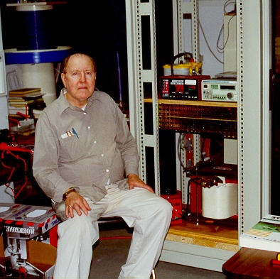


                            I join Soundiceuk and others in saluting Don and have the greatest respect for those who continue to experiment.

                            Ged

                            Comment


                            • [QUOTE=Gedfire;223839]
                              Originally posted by soundiceuk View Post

                              Typically Don fell into the trap of wanting to make money from his devices and unfortunately later in his life became delusional.


                              Agreed,I believe he did.


                              I would say Don meant business when he said the materials are pitched to a point were the sharp ones can figure it out! (Mr. Clean? Janost etc? Nice!)


                              In the latest 2005 Videos photos are displayed.Battery,50F Cap and Inverter.Did you know that the tower device appeared to have used two inverters? The 600W one to power the PSU and the homebuilt middle piece to send power to the Big Indian made output transformer.

                              How do I know? well the other older video with the dielectric testing demo at the end had a presentation at the beginning.LISTEN carefully as the narrator said, that some of the compressed waveforms were from TWO inverters.


                              He speaks real fast so listen well.[/COL
                              Hello Gedfire,

                              Clarence,

                              I am not familiar with the tower device you are speaking of? maybe I missed something somewhere! do you have any specific link info on the tower device you are speaking of? I would sure like to have that info if possible. Thanks again, mike, onward!

                              Comment


                              • Originally posted by clarence View Post
                                Hello Gedfire,
                                Clarence,
                                I am not familiar with the tower device you are speaking of? maybe I missed something somewhere! do you have any specific link info on the tower device you are speaking of? I would sure like to have that info if possible. Thanks again, mike, onward!
                                I think he might be referring to this device with the big variac and big custom made transformer, which is mounted in an industrial style equipment rack:

                                Last edited by level; 02-04-2013, 03:20 AM.
                                level

                                Comment

                                Working...
                                X