Announcement

Collapse
No announcement yet.

Donald Smith Devices too good to be true

Collapse
X
 
  • Filter
  • Time
  • Show
Clear All
new posts

  • Originally posted by Grumage View Post
    Dear Graham (GSM).
    I would like to thank you for presenting the most understandable process of NMR that I have ever read. Well done.
    Are you able to provide us with a simple drawing of how such a device could be constructed?
    My own thoughts are thus. Inner tube wrapped with the "Gain media" be it Copper Steel or Aluminium tape, spiral wound the length of tube. Over this tube a coil wound the full length to provide the excitation. And then a final pair of coils to provide the essential magnetic field for the gain media.
    The above paragraph will sound familiar to most of us as this is how most schematics are portrayed. Now have I missed something??
    Your thoughts??
    Cheers Grum.
    Yes it is likely that the most effective resonance would be NMR, though with the induction of this pulsed either by a relay as in Serg's last circuit, or via an electro-magnetic vibrator arrangement as with Hendershot, or via a separate solid state oscillator as with Dunfasto's circuit drawing.

    Your "Gain media" ? I keep mentioning iron for this, and copper can be used, maybe even tin; but I would not recommend aluminium as the inner source in case it would become converted into magnesium and burst into flames with the heat. Use of aluminium for outer windings would likely be fine.

    Akula already has good devices, and I would not be surprised if his circuits are very similar to those shown by Serg and Dunfasto. Personally I am going to stick with the Hendershot design as it does not spark generate longitudinal fields, and transduces any possible beta radiation with aluminium foil.

    Cheers ............... Graham.

    Comment


    • quote from Beamgate: What a tiresome assertion from the teacher! Clearly the delivery of your 'message' was lost. Why?


      Possibly it was lost because some and maybe even most of us have been and are still being brainwashed into thinking otherwise. Not listening or really hearing what people like Tesla, Kapandze, Walter Russel, Viktor Schauberger, and many of the other non-mainstream free thinkers have repeatedly mentioned.
      The best example of this lack of judgement is the "Big Bang Theory". Which is still upheld, and even still taught to your kids in school, as FACT.
      Is this what our best scientist think? REALLY!!!

      I'm not asking any one to believe me, as I may be wrong.
      But, you take into account and marvel at what Tesla has stated, built, and patented, yet, still don't believe what he said to be true.


      GSM: You mentioned "orbiting electrons", then mentioned "electron spin", electron flow, etz... How about considering vortex spin, and it's field effects on everything at hand. Again, I recommend re-reading up on Tesla's concepts.
      Because if anything is actually spinning or moving, it's because there is an influence (from the outside) making it do so. As a non living material object has no power to do anything, on its own behave, but is subject to "field effects".
      Again, my suggestion is also to read up on the Vortex Theory.
      You may find it to be no theory at all, but something very real, instead. And possible more believe-able than the Big Bang, stating that Everything came from nothing, in an instant...
      Last edited by Nick_Z; 10-12-2013, 05:43 PM.

      Comment


      • It's simply like this : you can have resonance and keep it and still have kW output while resonance is ticking almost untouched....why Tesla never said about it is beyond my comprehension . Maybe he was not so saint ? Some remarks left in his articles and lectures seems to prove he knew or at least was near the solution in 1890. Then in 1895 his lab was destroyed by fire. Strange. Or maybe he found the solution really too late in 1930 when he mentioned he finished his 25 years long work on cosmic rays.Or maybe he wanted to complete his greatest dream ....

        Comment


        • Originally posted by Nick_Z View Post
          The best example of this lack of judgement is the "Big Bang Theory".

          GSM: You mentioned "orbiting electrons", then mentioned "electron spin", electron flow, etz... How about considering vortex spin, and it's field effects on everything at hand.
          Because if anything is actually spinning or moving, it's because there is an influence (from the outside) making it do so.
          Again, my suggestion is also to read up on the Vortex Theory.
          I have thought Big Bang and speed of light limitations as two of the worst scientific mind control ideologies perpetrated by so called 'scientists'.

          Yes, electron spin + spin axis precession + full spin axis rotation induced via a field vortex are what I have been writing about. First mentioned a year ago in my Hendershot thread, this before I realised that all prior non-radioactive 'free energy' devices operated in this way; as here too.

          The tricky part is the generation of that vortex field at the surface of some core metal, for it takes more than one impulse or field to do this, such that there are two or three fields, with one or two impulsive, and all controlled in a timed or phased or resonant pattern.

          In my last post to Grum I mentioned iron/steel for the core material, but forgot to mention another point in its favour, the most important attribute for relatively low NMR frequency working.

          Cheers ............. Graham.

          Comment


          • RED DEVICE !!!!


            ps: Большинство считают, что все сложно постигаемое должно быть очень глубоким. Это неправильно. То что трудно понять, это то, что незрелое, неясное и часто ложное.
            Высочайшая мудрость проста и проходит через мозг прямо в сердце.
            В. Шаубергер.


            Majority ofl people take comprehend opinion that all in complicated manner must be very deep. It's wrong. All what is difficult for understanding is half-baked , vagueness and offen frequently FALSE.
            Very high wisdom is very simple and go through mind straight to the heart
            Victor Schauberger (simple forestry officer and Genius Austrian Inventor of 20 century.)

            Comment


            • Originally posted by GSM View Post
              Yes it is likely that the most effective resonance would be NMR, though with the induction of this pulsed either by a relay as in Serg's last circuit, or via an electro-magnetic vibrator arrangement as with Hendershot, or via a separate solid state oscillator as with Dunfasto's circuit drawing.

              Your "Gain media" ? I keep mentioning iron for this, and copper can be used, maybe even tin; but I would not recommend aluminium as the inner source in case it would become converted into magnesium and burst into flames with the heat. Use of aluminium for outer windings would likely be fine.

              Akula already has good devices, and I would not be surprised if his circuits are very similar to those shown by Serg and Dunfasto. Personally I am going to stick with the Hendershot design as it does not spark generate longitudinal fields, and transduces any possible beta radiation with aluminium foil.

              Cheers ............... Graham.
              Dear Graham (GSM).

              Many thanks for your reply to my post. I noticed you put a question mark after the term " Gain media". Is this not the correct term for such?

              I have made an attempt to replicate the Akula device, my version also had a form of Hendershot style inner sleeve. This sleeve consisted of a pair of rolled Aluminium split tubes and an insulator between them. It had a capacitance of 6 nF. When in parallel with an internal choke of 250 turns (approx.) And driven by the primary oscillator this pair (LC) resonated at it's own frequency irrespective of the drive frequency. I was also able to raise several Kv, measured by a ten turn (very well insulated) pickup coil placed near the base of the choke.

              Whilst my setup could drive as many lamps as was seen fit to try the device never reached a state of OU!! You can see the results here...........


              https://www.youtube.com/watch?v=LOqjTHmmumU

              I have had an interesting life and one of my Hobbies was the restoration of early farm Stationary engines. Some of these employed a Trembler box to provide the HT ignition. Now a bit of lateral thinking....... One of these could be used to provide both a pulsing low frequency signal and the secondary coil give an EHT output of several Kv!! And they would also be in synch with each other!! Just a thought??

              Cheers Grum.

              Comment


              • simple sr coiling not needing ground one can test the intensity of bulb by attaching ground wire to one of bulb legs to see difference plus or minus effects.


                sr connections Pictures, sr connections Images, sr connections Photos, sr connections Videos - Image - TinyPic - Free Image Hosting, Photo Sharing & Video Hosting

                dunfasto

                Comment


                • Originally posted by Grumage View Post
                  Dear Graham (GSM).

                  Many thanks for your reply to my post. I noticed you put a question mark after the term " Gain media". Is this not the correct term for such?

                  I have made an attempt to replicate the Akula device, my version also had a form of Hendershot style inner sleeve. This sleeve consisted of a pair of rolled Aluminium split tubes and an insulator between them. It had a capacitance of 6 nF. When in parallel with an internal choke of 250 turns (approx.) And driven by the primary oscillator this pair (LC) resonated at it's own frequency irrespective of the drive frequency. I was also able to raise several Kv, measured by a ten turn (very well insulated) pickup coil placed near the base of the choke.

                  Whilst my setup could drive as many lamps as was seen fit to try the device never reached a state of OU!! You can see the results here...........


                  https://www.youtube.com/watch?v=LOqjTHmmumU

                  I have had an interesting life and one of my Hobbies was the restoration of early farm Stationary engines. Some of these employed a Trembler box to provide the HT ignition. Now a bit of lateral thinking....... One of these could be used to provide both a pulsing low frequency signal and the secondary coil give an EHT output of several Kv!! And they would also be in synch with each other!! Just a thought??

                  Cheers Grum.

                  buzz a coil using relay and flyback.

                  attaching different caps with different capacity make relay vibrate with different frequencies.

                  one can find suitable cap for 50 hz

                  Buzz Coil Flyback HV Generator

                  Magneto Ignition for Gas Engines - Buzz Coils

                  note : attach rf capacitor in pf range to supress rf and avoiding pitting of points of relay make and break contacts.


                  dunfasto
                  Last edited by dunfasto; 10-12-2013, 11:19 PM.

                  Comment


                  • Originally posted by Grumage View Post
                    Dear Graham (GSM).

                    Many thanks for your reply to my post. I noticed you put a question mark after the term " Gain media". Is this not the correct term for such?

                    I have made an attempt to replicate the Akula device, my version also had a form of Hendershot style inner sleeve. This sleeve consisted of a pair of rolled Aluminium split tubes and an insulator between them. It had a capacitance of 6 nF. When in parallel with an internal choke of 250 turns (approx.) And driven by the primary oscillator this pair (LC) resonated at it's own frequency irrespective of the drive frequency. I was also able to raise several Kv, measured by a ten turn (very well insulated) pickup coil placed near the base of the choke.

                    Whilst my setup could drive as many lamps as was seen fit to try the device never reached a state of OU!! You can see the results here...........


                    https://www.youtube.com/watch?v=LOqjTHmmumU

                    I have had an interesting life and one of my Hobbies was the restoration of early farm Stationary engines. Some of these employed a Trembler box to provide the HT ignition. Now a bit of lateral thinking....... One of these could be used to provide both a pulsing low frequency signal and the secondary coil give an EHT output of several Kv!! And they would also be in synch with each other!! Just a thought??

                    Cheers Grum.
                    use ferrite yoke in your setup and replace the rectangular ferrite that you used in your video.

                    dunfasto

                    Comment


                    • Here is another Akula type of device replication by a poster on OU.com by the name of GeoFusion. His device is using a tv yoke, Royer oscillator, running on a 12 volt car battery, and is able to light 3 100 watt incandescent bulbs, at least partially. He mentions that the device can produce more output than just that much, although he has not shown that yet.
                      He is also going to make a new video, with a diagram, and more explanations.
                      This is more light output than I've been able to obtain from my version of the first Akula device (ver. 1). His device is also drawing more current as well, he said between 1 to 2 amps, at 12v. Still, not bad at all...
                      He also mentions that he was able to connect a feed back circuit, through a rectifier, and recharge the run battery.
                      Sounds good to me, so I asked him to make a better video, with better light, a steadier camera, and giving some more explanations as well.
                      He said that he would do so. Also mentioned that he has other similar devices but with much better output, as well.
                      Here's his video:
                      GeoFusion:
                      2013 RoundCore 12V oscillator output 300W - YouTube

                      Comment


                      • thanks for this

                        Originally posted by Nick_Z View Post
                        Here is another Akula type of device replication by a poster on OU.com by the name of GeoFusion. His device is using a tv yoke, Royer oscillator, running on a 12 volt car battery, and is able to light 3 100 watt incandescent bulbs, at least partially. He mentions that the device can produce more output than just that much, although he has not shown that yet.
                        He is also going to make a new video, with a diagram, and more explanations.

                        This is more light output than I've been able to obtain from my version of the first Akula device (ver. 1). His device is also drawing more current as well, he said between 1 to 2 amps, at 12v. Still, not bad at all...
                        He also mentions that he was able to connect a feed back circuit, through a rectifier, and recharge the run battery.
                        Sounds good to me, so I asked him to make a better video, with better light, a steadier camera, and giving some more explanations as well.
                        He said that he would do so. Also mentioned that he has other similar devices but with much better output, as well.
                        Here's his video:
                        GeoFusion:
                        2013 RoundCore 12V oscillator output 300W - YouTube
                        thanks for this.looks promising.

                        Comment


                        • Originally posted by Gedfire View Post
                          thanks for this.looks promising.
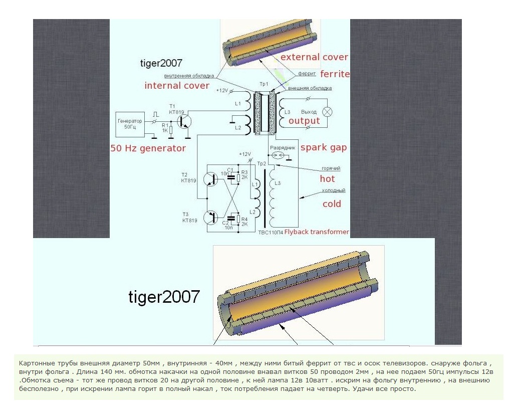
                          Original Tiger2007 OU 1kWatt schematic


                          TIGER2007 OU LABARATORY


                          Искрить надо так

                          turn on oscillograph with 50kV HV probe, tune device to get correct oscillogram.

                          Oscillograms
                          обратная связь по питанию - YouTube

                          Два резонанса - YouTube

                          параметрическая накачка высокой частотой - YouTube

                          YouTube

                          110221-001535 - YouTube

                          110122-173912 экономайзер - YouTube


                          Tiger 2007 22.05.2011 г.

                          More info on Russian here: http://freeenergylt.narod.ru/index/0-46

                          Comment


                          • Interested but not sure

                            Hello Serg and everybody. I wanted to try the Relay in a buzzer circuit breaker mode, but im not sure how it is wired. Could you show me a simple picture or link of a circuit diagram on the Relay of Red's Device. The position of the Capacitor which makes me confuse.

                            Any suggestion for value or link of how can I calculate 60Hertz on the Relay Circuit would be much appreciated. Thank you in advance. I think the position of the capacitor on the relay is the same on configuration of Tigers's Device this is indeed a simple configuration of Impulse Technology.

                            Stupify:

                            Originally posted by GSM View Post
                            Hi Serg.

                            "in working 'on' state the relay must interrupt DC voltage, not make contact"
                            = no power mosfet current = no "silent bluish sparks" ! ....... ?????

                            Cheers .................. Graham.

                            Comment


                            • Originally posted by dunfasto View Post
                              use ferrite yoke in your setup and replace the rectangular ferrite that you used in your video.

                              dunfasto
                              Dear dunfasto.

                              With respect, I fail to see how replacing my Ferrite cored transformer with "any old yoke" from a TV would have any bearing on my results. After all it would appear that the only yokes that seem to have an OU effect are the Russian ones!! The yoke is, after all, just a transformer with a centre tapped primary and two secondary outputs!!

                              I don't like to disagree with you but this is the way I see it!! I am well aware that the Yoke that was used by Tiger, T-1000 and Wesley in their Lithuanian experiment was of a Barium Ferrite nature which is known for it's OU effect.
                              And it is quite feasible that Akula's yoke is also a Barium one.

                              But that said Akula has stated that the energy generated by his device is a direct result of NMR, the Copper windings being the source of "Fuel" in this case.

                              Cheers Grum.

                              Comment


                              • Originally posted by stupify12 View Post
                                Hello Serg and everybody. I wanted to try the Relay in a buzzer circuit breaker mode, but im not sure how it is wired. Could you show me a simple picture or link of a circuit diagram on the Relay of Red's Device. The position of the Capacitor which makes me confuse.

                                Any suggestion for value or link of how can I calculate 60Hertz on the Relay Circuit would be much appreciated. Thank you in advance. I think the position of the capacitor on the relay is the same on configuration of Tigers's Device this is indeed a simple configuration of Impulse Technology.

                                Stupify:
                                Hi Stupify.

                                The relay must be a fast type.
                                It is being fed with half wave rectified AC = half cycle on + half cycle off.

                                Hi Grum,

                                So Akula has said that the copper itself is the fuel.
                                At last.
                                This is Cu to Ni isotope, as I suggested with Fe to Mn isotope in the Hendershot generator,
                                and where beta emission release induces an Auger electron avalanche.

                                Cheers ............... Graham

                                Comment

                                Working...
                                X