Announcement

Collapse
No announcement yet.

Donald Smith Devices too good to be true

Collapse
X
 
  • Filter
  • Time
  • Show
Clear All
new posts

  • Hi Clarence and All,

    I'm checking your B&L replication. First of all, thank you for all your work
    So, you said to use toroid transformer. Two of them and i saw the order detail (bill) for those thing TD300-1120-P 125$ On this reciept the order detail was just for one toroid not two.

    And on the B&L2.JPG you just sent, we can see one toroid is clockwise and the other is anti-clockwise wound at the primary. So we need 2 differents toroid ? On another site you said and i quote:"both toroid HAVE to be identical!!!!"

    I will do your replication, but before ordering anything i just want to be sure.

    Thank you again.


    SORRY I FOUND my ANSWER. Just put the toroid up side down and invert input lol. Toroid are identical. I'm shy now lol too easy
    Last edited by Yanmar; 04-26-2015, 09:58 PM. Reason: I found my answer

    Comment


    • Originally posted by boguslaw View Post
      Don Smith : "generators don't make electricity"

      Harry Perrigo : ""The device is a generator as truly as the power-driven rotary generator in any power plant. Those generators don't actually 'make' electricity. They condense it from the air."

      "In 1919 Hubbard represented the apparatus as being capable of extracting electrical energy directly from the air"

      Hendershot : "His earlier invention was called a "motor" by the newspapers, but it was actually a generator which was powered by the magnetic field of the earth. His later models created enough electricity to simultaneously light a 120 volt light bulb and a table model radio."

      and so on
      I found a few more where small disturbance might be involved and the back and forth action is facilitated.
      The consensus lately leaning toward the the effect performed at a resonant coil. In this video a matching coil on right
      increases the coil on the left ? Ambient background the near field of the yellow primary ?

      https://www.youtube.com/watch?v=D7QiI8p1gi4

      while the Bill Alek device increases at the coil but he thought it might be due to transmutation at spark gap due to carbon.
      HV electrical discharge into a Tesla like inductor that allows the pulse to travel back and forth.
      A small HV discharge near field of the primary ? And with Don Smith it's anywhere in the neighborhood.
      Could mean the disruption field even small would functions more as a communicator to the aether and resonant coils.

      https://www.youtube.com/watch?v=MKfebTL2iiY
      Last edited by mikrovolt; 04-28-2015, 03:04 AM.

      Comment


      • Research and Development

        Good to see you guys discussing Don's work. Keep it up.For me, I have not given up and don't plan to anytime soon.
        Thats why I check in once in a while.

        Comment


        • Originally posted by mikrovolt View Post
          I found a few more ..........

          https://www.youtube.com/watch?v=D7QiI8p1gi4
          Okay one suggestion please. Make the small coil flat just like it is.

          Next make the bigger coil a bifilar flat coil.

          Next you will be getting the extra. Remember that Don S. used

          coils with taps. Maybe like a bifilar. But either way whenever

          you pump energy using and inverter coil, also use a Tesla Bifilar

          for the receiver.

          My opinion. Take it or leave it but if you have never tried

          that, what do you have to lose?

          The GeGene works like that.

          Here is a good video for you

          https://www.youtube.com/watch?v=hQVfW1yUqTo

          https://www.youtube.com/watch?v=ghnoFpY0-hQ


          https://www.youtube.com/watch?v=i3fL1BdN9aU
          Last edited by BroMikey; 08-08-2015, 06:45 AM.

          Comment


          • Thats the attitude!

            Originally posted by BroMikey View Post
            My opinion. Take it or leave it but if you have never tried

            that, what do you have to lose?

            Comment


            • Think how radio waves were first detected ....

              Comment


              • Originally posted by level View Post
                Hello a.king21. I spent a fair bit of time studying Don Smith's documents and videos, and doing a number of experiments, and I also could not reproduce anything that indicated over unity. Also Don Smith has said a few things that seem to be clearly wrong from a technical point of view, which does at least call into doubt much of his other claims.

                Don's apparent first over unity demonstration setup was the board with the one transmitting tesla coil, surrounded by other receiving tesla coils. Don Smith claimed that each of the receiving tesla coils would receive a duplicate of the power being transmitted by the transmitting tesla coil, giving a total output power that is over unity, but in tests I did with this setup, the power being applied to the transmitting tesla coil actually divides amongst the receiving tesla coil loads, as would be expected in conventional theory.

                Don claimed in one of his videos that a neon sign HV transformer (NST) was an over unity device in itself since if you multiply the output voltage and current ratings on the NST you get a power rating greater than the rated max input power consumption rating of the NST. This is clearly wrong however because the output voltage rating on an NST specifies the max open circuit output voltage for the NST, and the output current rating on the NST specifies the max short circuit current rating of the NST. You can't multiply these two values together. That doesn't make any sense and anyone with a basic understanding of electronics should realize that.

                Don also claimed in the Bonus video that you could connect the HV secondary output wires from an NST directly to the primary of a tesla coil to drive his 'simple over unity' setup, but again for anyone who understands about NST's and transformers in general, such a connection between the NST output and a tesla coil primary would look like very close to a short across the NST, and the NST would not be able to drive the tesla coil primary that way.

                Don also claimed that you can place a resistor across a transformer primary and change the frequency at its output. You could maybe lower the resonant frequency of a transformer primary a bit that way, but that does not appear to be what Don Smith was referring to when he spoke about this. Don Smith seemed to think that you could just apply different resistors across a transformer primary and change the frequency of the waveform at the output. In the general case, that will just not work. If Don did mean this for some special case, it was not clear at all to me what that was.

                Whether Don Smith really made some over unity devices I don't know, but some of the claims Don Smith made certainly don't make sense or don't stand up to basic testing. Don Smith did seem like a very sincere guy, so I think that is why some people may find it hard to imagine that the things he was saying may be wrong, but certainly the four items I mention above are just plain wrong, or at best very questionable for one or two of them.

                Hey level....what you say here is very disappointing for me because at this moment I am trying to replicate the same setup with one emiter coil and few receiver coils like you did....also I observed ,in my experiments,the same effect using the output nst ( in fact ZVS circuit driving a tv flayback transformer ) directly at the primary tesla coil -don smith sugestion- without clasical capacitor-spark gap setup to triger primary ; no energy transfer in secondary at all... if we driving primary with high voltage ,low current , in secondary will be no energy transfer......we need amperage or at least capacitor-spark gap combo....

                Anyway, I think the Smith setup with emiter and receiver coils are not fake...kapanatze did the same setup in Turkey at bigger scale :Kapanadze 100 Kw 2007 Tmz Turkey 3 4 5.24 (MB) | MP3 Top Songs must be a trick somewhere that we cannot catch yet...
                CAn you please share more details about your setup? Did you coupled the receiver coils with emiter coil wireless via resonance? Can you let me know how you have made the tunning betwen coils? You have used variable capacitors across receiver coils to tuned them? At the emmiter coil you have used spark gap-capacitor combo for trigering primary?Smith says primary must be 1/4 shorter than secondary for easy tuning ;you have used this procedure in your setup? Can you please give me more details about tunning procedure to help me tune my coils ? I am prety new in this kind of experiments with tesla coils -smith and resonance tuning

                Some drawings it would be helpfull ....
                Thanks

                Comment


                • about kapanatze

                  One more think....now few weeks ago , I spoken via mail with romerouk ..
                  He told me about a turkey guy who bought from kapanatze a free energy device with 5000 euros ( around 2-3 kw power if I remember) ...he couldn't
                  give details and pictures about device because that was the understanding between kapanatze and that guy but also he invited romerouk to go and see the device ... at that time the guy was in Leipzig ... if somebody live in that area can take contact with the guy ,maybe we can bring out more details if the turkey guy will let us to watch his system....

                  Comment


                  • wrong voltage to inverter will completely destroy it! Look again at schematic given!

                    In your hand written schematic, you show the 8kV output feeding into a voltage divider, then, you give formula and sizes which drop the voltage to 120vac, not what it's supposed to be, 12 volts. First , the voltage driving the inverter needs to be fed with 12 volts, not 120v, or, you'd need to feed the 120v output into a very powerful 120v to 12 volt dc power supply, however, there isn't a resistor on the planet with a high enough wattage rating to output even a few thousands watts, even though the resistances are split in the divider, they would have to split the wattage accordingly, and that would equate to 8000v output to r1 being the resistance needed to split the high voltage(r1=100kOhms) r2 needed to arrive at 118 v. The wattage at the first resistor, if the high voltage would output only .078 amps would equal 621.223519 watts. The wattage at r2 for the low voltage output would be 9.318353 watts (10 watt resistor is easy to find, but, how about the 650 watt resistor needed for the HV? the largest Ohmite resistors they have available online are maybe 150 watts. If the output is this high, split between both resistors, the best output we'd be able to get is maybe 159 watts without smoking the resistors. and, if we hook it up according to the schematic, the inverter would get fried, probably destroying the power supply of the inverter because the voltage is 10 times higher than it needs to be at nearly 120 volts ac.

                    My suggestion would tbe to use a utility transformer, a single phase residential transformer, maybe a 15kva unti that's normally operational at 7970 volts at the high side bushing and eliminate the resistors completely because they will waste energy, dissipate heat and cost more than a refurbished transformer, however, I would hate to say that the circuit probably wouldn't have enough juice to driive the coils because the output is supposed to increase as the circuit is loaded. The voltage divider I think is an awful way to do this.. If you look at Don's circuit, I don't think this is a voltage divider, and, if it is, both sides of it appear to be made of the same material and the same sized windings, not making sense to be merely resistors but rather inductors of a specific size. If they are equal, it would mean the voltage would be split in half and if you look close at the color of the pvc tube used, it did get very hot. I would imagine that he either wound his own divider, and, if he did, one side had to have used so much of am extremely resistive material, and very little of another, again, they both look identical.

                    If the circuit outputs cold electricity, we know that resistance works in the opposite manner according to Karl Palsness, and, if this is the case, we obtain more power from higher resistances than lower and the formula you have given here is conventional, as well will be useless because it will NOT equate to the same as what you say. We would need to speak with Karl to figure out the correct resistances at that voltage to get a power output in any suggested range. Since the material used in the output coils seem to be copper, I think we could mimic the windings and just try it to see what it is doing.. however, I do not see any resistors used on Don's board making the suggestion to use resistors and absolute ridiculous idea.

                    Comment


                    • Hello everyone,


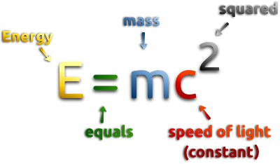
                      before going so far with Don Smith technology we must realize an unique condition, it imply the attraction of ambient electrons with radio frequency speed, the energy equation of his device look like the famous energy equation :


                      the above formula is achieved when we divide the atom..., in Don Smith device we must divide the electricity into two equal portion according electrons spin rotation... the device with this ability is the extended Tesla Bifilar coil, this device works against Lenz's law because it's not a closed circuit ... it's an open parallel LC circuit that must pass through serial resonance to continue its oscillation, when it do this both voltage and current are combined to give a useful electric power.

                      Comment


                      • Lowering instead of raising the voltage

                        Originally posted by Dave45 View Post
                        I guess you could say their counteracting the bemf, its working with what we call bemf instead of working against it.
                        And yes the voltage may need to be stepped down, but remember Don said you could lower the input and therefor lower the output if the voltage and amps are sufficient.
                        Dave
                        I saw a video on youtube showing a ZVS firing a Don Smith generator. In this setup the designer used only a step down system and it worked better than any I have seen except for the Japanese guy, who reproduced Don's system entirely with multiple bulbs, the whole nine.

                        I've been messing with the same system that Don has shown online, I have tuned to resonance, I used the caps he has in his device, wound the coil the same as he says, used the calculations and nothing worked. I changed the way the spark gap was installed and I had only a dim output which was a 100w incandescant bulb lit up like a 10 watter with shades on. I tried it all , then, I found a post where Don stated that his storage capacitors were custom built by Cornell capacitor and they were not able to be found on the market anywhere. I contacted the factory and I found the size of the cap. Since Don ran his own R&D company., Cornell Dublier sent him a sample of the caps free and they were an astronomical size that doesn't exist for less than 8k $. I have found the right combination, however, Don relates everything to the Farad, even the calculations, not the microfarad. That is the problem.. HV caps are not sold in any denomination over 2.7v, and, even if they were, to get enough HV caps or large enough caps to dam the river of energy enough to give the amperage necessary, we need to ensure they are good for the storage ofextremely high frequencies, where many caps fail here, then, after they store the charge, we filter it's output for a bandwidth of 58.5hz to 60.5 hz to allow the step down transformer's impedance to be used for the calculation of the bandpass filter needed to filter out the massive bandwidth that needs to be eliminated. Here's the secret of how it becomes an overunity devices. and it is absolutely the rule of thumb here. The energy in the megahertz range is so wide that the energy attracted to the coil is exponential and can be used if the caps are correct and large enough oil filled high frequency absorbant type caps to allow the energy to store, then, the energy is released and only a small fraction of the frequency is taken from the cap at great force, allowing the cap to slowly discharge at a very high and dangerous amperage. If we send the power into the cap at say 200 MHZ and remove it leaving everything stored from 0 hz to 58.5hz , then again from 60.5 and up is left alone , we then have just eliminated all of that excess power fed into the unit and used only 1/100000th of the energy to do some pretty enormous work since we are driving a system of conventional electricity with a tiny little input (the caps aren't holding the frequencies, they are actually filtering out low frequencies that are ultra inefficient, however, I am just giving an example of how little energy is used from it's input to create hundreds of thousands of watts in an incredibly unorthodox method. When we use a step down transformer to go from high voltage, stored in the caps, we then have to measure the impedance of the primary coil of the transformer. Another neon transformer can be used, however, they are not good for any type of amperage, but, a real utility transformer is good to use, if the frequency is 60 hz.

                        My method is to step up from the nst to 8kV per coil side, upper and lower. The upper is used for amperage, lower for voltage. If we favor the top, we gain amperage and have a lower voltage. We then have to store the energy and step it back down. I haven't had success using pulsed dc, so, we can do the same with an ac sinewave, then, arc and fire the load as well as the input coil because the arc pushes out a massive electromgnetic pulse at the bloch wall of the secondary coil.

                        If we drilled a hole in a homemade plate capacitor, added thick plastic sheeting and wound the amperage side of the secondary coil at the bottom of the capacitor plates, we could use a 50mA function generator at 20 volts to drive a resonant coil/transformer to get high voltages at the res frequency to change out the magnetic pulses at the top of the hv coil to transfer into high amperage usable electricity that is filtered in the opposing manner, low frequencies only and down at the output in a range of like 50 to 100 kVA. That is nothing to sneeze at either, and, it blows away what the capacitor and coil generator made, it is so simple. Don shares this, Vladimir Utkin shares it and I have built one from a Lava lamp that outputs 2200 watts using less than 2 watts of input power. Now that is incredibl;e and it is extra easy!

                        Don loved the 12v neon transformers because he said it was a home run everytime and no resonance was needed from caps, just a 1 to 4 ratio for 1/4 waves and the system outputs through a varactor to the output, from the 120v to 230v output, back to 12 volts with a battery charger circuit to give the battery back what was necessary and the step down transformer is not needed, just a simple computer ups system for maybe 300 watts or simple cheap 150w inverter to make nearly a megawatt. Now that is insane.

                        Comment


                        • Originally posted by Belangers View Post

                          I've been messing with the same system that Don has shown online, I have tuned to resonance, I used the caps he has in his device, wound the coil the same as he says, used the calculations and nothing worked. I changed the way the spark gap was installed and I had only a dim output which was a 100w incandescant bulb lit up like a 10 watter with shades on.

                          I tried it all , then,

                          I found a post where Don stated that his storage capacitors were custom built by Cornell capacitor and they were not able to be found on the market anywhere. I contacted the factory and I found the size of the cap.


                          Since Don ran his own R&D company., Cornell Dublier sent him a sample of the caps free and they were an astronomical size that doesn't exist for less than 8k $.


                          I have found the right combination,

                          however,

                          Don relates everything to the Farad, even the calculations, not the microfarad. That is the problem.. HV caps are not sold in any denomination over 2.7v, and, even if they were, to get enough HV caps or large enough caps to dam the river of energy enough to give the amperage necessary, we need to ensure they are good for the storage of extremely high frequencies, where many caps fail here,

                          then,


                          after they store the charge, we filter it's output for a bandwidth of 58.5hz to 60.5 hz to allow the step down transformer's impedance to be used for the calculation of the bandpass filter needed to filter out the massive bandwidth that needs to be eliminated.
                          Originally posted by Belangers View Post

                          Here's the secret of how it becomes an overunity devices. and it is absolutely the rule of thumb here.

                          The energy in the megahertz range is so wide that the energy attracted to the coil is exponential and can be used if the caps are correct and large enough oil filled high frequency absorbent type caps to allow the energy to store, then, the energy is released and only a small fraction of the frequency is taken from the cap at great force, allowing the cap to slowly discharge at a very high and dangerous amperage.


                          If we send the power into the cap at say 200 MHZ and remove it leaving everything stored from 0 hz to 58.5hz , then again from 60.5 and up is left alone , we then have just eliminated all of that excess power fed into the unit and used only 1/100000th of the energy to do some pretty enormous work since we are driving a system of conventional electricity with a tiny little input (the caps aren't holding the frequencies, they are actually filtering out low frequencies that are ultra inefficient, however,

                          I am just giving an example of how little energy is used from it's input to create hundreds of thousands of watts in an incredibly unorthodox method.

                          When we use a step down transformer to go from high voltage, stored in the caps, we then have to measure the impedance of the primary coil of the transformer.

                          Another neon transformer can be used, however, they are not good for any type of amperage, but, a real utility transformer is good to use, if the frequency is 60 hz.

                          My method is to step up from the nst (Neon Sign Transformer) to 8kV per coil side, upper and lower. The upper is used for amperage, lower for voltage. If we favor the top, we gain amperage and have a lower voltage.

                          We then have to store the energy and step it back down.


                          I haven't had success using pulsed dc,

                          so,

                          we can do the same with an ac sinewave,

                          then, arc and fire the load as well as the input coil because the arc pushes out a massive electromgnetic pulse at the bloch wall of the secondary coil.

                          If we drilled a hole in a homemade plate capacitor, added thick plastic sheeting and wound the amperage side of the secondary coil at the bottom of the capacitor plates, we could use a 50mA function generator at 20 volts to drive a resonant coil/transformer to get high voltages at the res frequency to change out the magnetic pulses at the top of the hv coil to transfer into high amperage usable electricity that is filtered in the opposing manner, low frequencies only and down at the output in a range of like 50 to 100 kVA.

                          That is nothing to sneeze at either,

                          and,

                          it blows away what the capacitor and coil generator made,

                          it is so simple.

                          Don shares this, Vladimir Utkin shares it

                          and


                          I have built one from a Lava lamp that outputs 2200 watts using less than 2 watts of input power. Now that is incredibl;e and it is extra easy!

                          Don loved the 12v neon transformers because he said it was a home run everytime and no resonance was needed from caps, just a 1 to 4 ratio for 1/4 waves and the system outputs through a varactor to the output, from the 120v to 230v output, back to 12 volts with a battery charger circuit to give the battery back what was necessary and the step down transformer is not needed, just a simple computer ups system for maybe 300 watts or simple cheap 150w inverter to make nearly a megawatt. Now that is insane.


                          Very good post and I can tell you know what you are talking about.
                          DAVE45 has not been around for sometime and has done very few
                          experiments that I know of, however DAVE45 did thousands of drawings
                          that he picked up from other people as his major contribution to alt energy.

                          This really rang a bell when you said to use an oil filled HV utility Transformer
                          because 2 men I know say they can use one of those to get huge
                          outputs with only a small input.

                          It would be helpful if you could show me these people you mention
                          youtube channel? or anything visual such as an experimental setup.

                          This is a very thrilling prospect to me. The HV and HF draws in the extra
                          I have heard over and over again.

                          I am at a loss for words other than asking which Don Smith diagram
                          did you see when you built your setup? There are 5 or more, and
                          DON is no longer with us.

                          It is good to hear from someone who is doing more than just speculating
                          that has built a rig that proves the theories. Thanks for sharing, you are
                          going down in history in my book and many others here.

                          It's posts like these that push me over the edge, so to speak.

                          I have reread your post and it is becoming very clear that the utility
                          transformer is used to step down the HV from the cap but you still
                          need a special capacitor?

                          What HV and HF capacitor did you end up with? And how much money
                          do they cost?

                          Last edited by BroMikey; 12-18-2015, 07:31 AM.

                          Comment


                          • Originally posted by Belangers View Post
                            My method is to step up from the nst to 8kV per coil side, upper and lower. The upper is used for amperage, lower for voltage. If we favor the top, we gain amperage and have a lower voltage. We then have to store the energy and step it back down. I haven't had success using pulsed dc, so, we can do the same with an ac sinewave, then, arc and fire the load as well as the input coil because the arc pushes out a massive electromgnetic pulse at the bloch wall of the secondary coil.

                            If we drilled a hole in a homemade plate capacitor, added thick plastic sheeting and wound the amperage side of the secondary coil at the bottom of the capacitor plates, we could use a 50mA function generator at 20 volts to drive a resonant coil/transformer to get high voltages at the res frequency to change out the magnetic pulses at the top of the hv coil to transfer into high amperage usable electricity that is filtered in the opposing manner, low frequencies only and down at the output in a range of like 50 to 100 kVA. That is nothing to sneeze at either, and, it blows away what the capacitor and coil generator made, it is so simple. Don shares this, Vladimir Utkin shares it and I have built one from a Lava lamp that outputs 2200 watts using less than 2 watts of input power. Now that is incredibl;e and it is extra easy!
                            So your method is the above? And no special cap that is expensive is
                            required?

                            Can you illustrate your homemade capacitor with a coil on it?

                            Does this look right? What size plates and how many as an approx.


                            Last edited by BroMikey; 12-18-2015, 09:55 AM.

                            Comment


                            • Don

                              [VIDEO]https://www.youtube.com/watch?v=W7GHqw7d1No[/VIDEO]

                              [VIDEO]https://www.youtube.com/watch?v=Mnoy2D4wuf8[/VIDEO]

                              [VIDEO]https://www.youtube.com/watch?v=CY8ruHg05_k[/VIDEO]

                              [VIDEO]https://www.youtube.com/watch?v=r573nf3-oWg[/VIDEO]

                              [VIDEO]https://www.youtube.com/watch?v=AMo84rbjirM[/VIDEO]
                              Last edited by BroMikey; 12-19-2015, 06:33 AM.

                              Comment


                              • Don devices


                                Comment

                                Working...
                                X