Announcement

Collapse
No announcement yet.

Donald Smith Devices too good to be true

Collapse
X
 
  • Filter
  • Time
  • Show
Clear All
new posts

  • Here is another TBC shape experiments done in France.

    Tesla's "WIRELESS TRANSFER OF ENERGY"


    Jean-Louis Naudin

    Here a test about the measuring the temperature of the OUTPUT COIL with 4180 W of halogen lamps used as loads.
    More infos at: The JLN Labs home page

    After having connected the load to the Tesla bifilar coil through some electrical plugs, put the coil on the middle of the induction cooker. Push the start/stop button and then the "function" button. By default, the delivered power on my induction cooker model is 2000 W, this is too much for this experiment : reduce the power to 1000 W with the (-) button.

    At the beginning, the LCD shows the E0 error code (No cookware on the plate, cookware not fitted for induction) with a bip. To build up the EM coupling of the output coil, you need only to place temporarily a sheet of magnetic metal (180x180mm) or a magnetic cookware above the coil and in the middle of the induction cooker. When the output lamps are lit you must remove quickly the metal sheet because this metal sheet will heat up very fast. Never maintain the cookware or the metal sheet on the induction cooker in this experiment. If everything has been done correctly the halogen lamps will light at high power. You may move the output coil so as to get the maximum of ligh induction cookert output. The flat bifilarTesla coil doesn't heat too much and you may move it without any problem with your hands.

    Tesla explains that a standard coil of 1000 turns with a potential of 100 volts across it will have a difference of .1 volt between turns. A similar bifilar coil will have a potential of 50 volts between turns. In that the stored energy is a function of the square of the voltages, the energy in the bifilar will be 502/.12 = 2500/.01 = 250,000 times greater than the standard coil!"

    This induction cooker buy on Amazon for only 39,90 €


    [VIDEO]https://www.youtube.com/watch?v=JqgO7AEZXzI[/VIDEO]

    Comment


    • Originally posted by BroMikey View Post
      I see this picture of an old Tesla patent and if anyone knows
      what the circled area is, let me know. Maybe that is half of the
      spark gap?

      Also I have posted this video
      that works something like one of DON SMITH'S devices in that
      one version DON had a small HV Tesla coil with 3 Tesla coil receivers.

      Always using a good earth ground. Naturally we all know that the
      circuits are used to drive the transmitter Tesla coil set and also
      used to collect energy from the receivers, converting it to a lower
      more usable voltage.


      [VIDEO]https://www.youtube.com/watch?v=hIqEHc9_Bwo[/VIDEO]


      [VIDEO]https://www.youtube.com/watch?v=5nxKqfkkndw[/VIDEO]
      Patent No. 568,178 figure 4 (circled area)
      According to the patent text it is simply a variable capacitor. used to adjust frequency. if closely coupled variation of capacity in secondary is similar in its effects to variation of capacity in primary. allows use of smaller capacitance for tuning than would be required in primary, according to patent

      Comment


      • Originally posted by Jeff Pearson View Post
        Patent No. 568,178 figure 4 (circled area)
        According to the patent text it is simply a variable capacitor. used to adjust frequency. if closely coupled variation of capacity in secondary is similar in its effects to variation of capacity in primary. allows use of smaller capacitance for tuning than would be required in primary, according to patent

        Thank You Jeff

        I did start to see this later and I am glad there is at least
        one person who is able to see clearly on these patent documents,
        that is interested in Tesla's work. I hear so many times that people
        feel the patents are all lies so why bother and so on.

        I don't feel that way at all, but these documents do take extra
        effort to read and not many are cut out for that work.

        This is the first time I have seen this particular patent and I think
        it is way over do that I read some of these. To begin to understand
        what they mean requires that I can follow basic diagrams with
        their component parts. This is a first step.

        Comment


        • Originally posted by qwekw View Post
          don smith resonant rise

          are you got these pages from this book?
          how u got it?
          Attached Files

          Comment


          • Further thoughts on patents US 568,177 (why I started looking at these) 568,178 etc. Notice there is not a spark gap. It looks to me like he is using the inductive kickback of his motor coils when they switch off as his disruptive discharge. When you pulse a coil by hand to light a fluorescent tube, the tube does not light when you apply power to the coil. It lights from the discharge of the coil when you remove power. It is as if you are using the capacitive effects of the coil to light the light. Maybe that is the direction we should go with this. How do we use coils as capacitors???

            Comment


            • Originally posted by Jeff Pearson View Post
              Maybe that is the direction we should go with this. How do we use coils as capacitors???


              this is what i am suggesting also, the coil and capacitor can be the same thing when energy balance is achieved, because the magnetic field has a closed induced electric field, we have to work with a bi-filar arrangement to conserve this field, when this is done magnetic resonance will be at hand, lenz's law can't be applied here because we are working in an open oscillating circuit ...

              Comment


              • Very interesting Qwekw.
                From which book are the pictures ? Od kojih knjizi su slike? Ono što je naslov knjige ?

                I recognise the video`s .

                Here Don Smith video : https://www.youtube.com/watch?v=Cr07kI7HhzU#t=3700

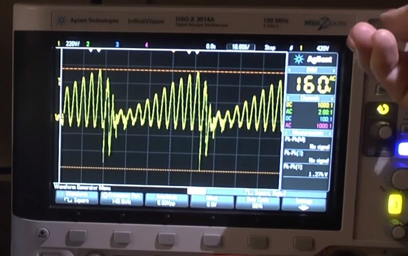
                But I think thats a different wave form than the wave form from ingener99 : see the video`s
                From Ingener99 Opposite Coils : https://www.youtube.com/watch?v=D7QiI8p1gi4
                and here Ringing Whale Wave 002 + schematic https://www.youtube.com/watch?v=itl-nFy_AT4

                I think there is an other wave form : that we have to look for.

                TheOldScientist on youtube has some video`s that are about negative resistance .. with a "nearly the same wave form" ... I think that is what we are looking for .. ...

                https://www.youtube.com/watch?v=JWD0Wy_UOEA#t=452
                https://www.youtube.com/watch?v=px14OF1D3EA#t=1145

                But probably we need both techniques in a working device .. but i do think these ar 2 different kinds of wave forms .
                Picture is from the video from TheOldScientist on YouTube.

                Well I am still learning .
                Last edited by Utopia Now; 01-14-2016, 12:25 AM. Reason: forgot to ask about the title of the book

                Comment


                • Looks like to me Tesla was building all of his devices out
                  of the same coil setup.


                  Comment


                  • Pictures are from this book
                    Attached Files

                    Comment


                    • Marc Belanger progres

                      Hey guys , seems Marc Belanger have made progres with don smith device on his video https://www.youtube.com/watch?v=CPgnKpScGDA
                      he made comments about his progress regarding don smith systems

                      Marc Belanger

                      Good news everybody. I have found the way to obtain resonance perfectly with the Smith device, so, I will be showing my followers a short video of how we obtain it, and, with capacitors, lock in what we need to have so no drifting happens as the transformer is not as critical as everybody thinks. The winding spacing is not critical, but, the spacing at the center is and an inductance meter is totally necessary to get the inductance once the separate coils are locked into a specific position. The primary has to be located within the Bloch wall area, dead center, and, at a 45 degree angle to the secondary to function. The primary wire has to be fine strand, 8 awg, silver coated copper 700 strand to 780 strand so the energy brought in has charge carriers at high frequency following the skin of each conductor. Each strand is considered to be one conductor, so, the ability of the amp king wire makes it function like nearly 250 litz wires used separately, giving the device an ability to do what Tesla's coils did. If we look in Tesla's experiments book, he shows that he can create a flux with one small tesla coil using an arc gap, a small primary and a secondary. He then creates a receiver, then, surrounding this device, he sets up several receivers within the flux path or the resonant coils in the same frequency. The more you can fit, because the transmission is at a radio frequency, the more power can be taken from it without affecting the load at the input. This allows a communication or "channeled communication" with the plasma tubes eminating from the Earth's poles up to the magnetosphere, where cosmic energy is induced within this flux, then, back to ground where at high frequencies, usually from 28khz to 44 khz, we can easily channel it, and, pick it up with devices such as receivers that can draw from slayer exciter circuits, tesla receivers, and, we have the ability to add more energy to the transmitter so it gives a larger "flux area" whixch gives a further broadcast distance, then, the receivers can be any amount of receivers that fit within the broadcast area and they will not add additional load to the input coil. It works like radio. We can transmit a 50,000 watt radio station, and, when we receive the radio signal and play it back, we do not draw any energy from it or deplete it. The radio signals gain energy from the layer of the atmosphere called the troposphere. The magnetic plasma tubes run from the poles of Earth, up to the magnetosphere, through all of the layers on their way up, and back down. Energy is drawn in from these channels of magnetism, allowing specific voltages to excite and move charges enough within coils of wire to create an attractive force between these layers of the atmosphere, chanelling the excess energies in as Tesla's receivers do. It is absolutely 100% true and possible, as it has already been completed by myself, Smith, Kapanadze and many others who have made these systems function. The grounding creates charge pumping of ionized particles into the ground, coming back out amplified when we use high frequencies. Whwn this energy is released back to the load, it comes as many times what we put in because the system operating creates an opposiong charge in the system at a nanosecond range that draws in positrons, positive particles from these layers of the atmosphere, inducing much energy and drawing an astounding amount of amperage in from the ground as the electrons start to flow at an awesome amount, far above what we put into the system. This only takes a small fraction of energy, in the milliamperes to drive the signal into the ground at high voltages which are enough to excite and ionize the air within the spark gap, we rectify this, we charge large cap banks up, and in a special way, we set the caps up, it allows us to discharge the caps at an overvoltage of their capacity without popping the caps because cold electricity is going into them, not allowing damage to the oil filled cap. The excess energy pours off at only the amount of voltage above the caps highest working voltage, so, an example would be the caps are rated at 1.2kV, we bank them in parallel and get maybe 100 uF or 200 uF instead of thousands, but, the voltage stays at 1.2kV, and we pump 30khz of say 9kV in, the caps dam the voltage and charge up to maximum and discharge 30,000 times per second, and, release energy closer to 500-800 volts and once we cut it with a 5000 amp Varistor rated at 240 volts, if we have the correct coil in it's output, with a very large conductor, we can get 240 volts at up to 250-500 amps out without ever harming the components, all dependent on cap size. Don Smith has stated that each Farad of capacitance has an ability to output 1000 watts with conventional power at 60 hz. When we increase the frequency, the charge happens exponentially per volt over the top of the voltage rating, so, we fill the caps more than instantly, it hapens as the amperage is being drawn from the caps so fast that we never run out of energy. I always thought that it could only stiffen this amount when used in a DC system, however, if the cap always stays charged while in use, it can't discharge unless we overload the system, and since we are damming a form of ac, which pulsed dc at high voltages is an ac voltage, we just do not have a sinewave until we filter it with a choke at the end of the circuit and apply a load to it. If we use the caps we have to remember, each cap used will give us it's wattage separately, like Tesla's coils do when receiving this energy. so, we will have in my case, 88uF caps x 6 at 1.2kV. each would equal a total of 1056 watts for each capacitor, so, 1056 x 6 will equal 6336 watts output. I have tested and verified this, and, i have found that the voltage left over in my circuit is 660 volts, cut after this output down to 240 v with a 5000 amp Varistor/240v 850 volt max operating voltage, and, the machine seems to be self correcting, however, when we use resistive loads, we need to be careful.. Cold electricity isn't what is output here unless we do not complete the circuit. Don's system is completed, and, if you look at the isolation xfrmer, it isn't large enough to run anything worthwhile, the output is the terminal strip, the iso xfrmr is the battery charger that he didnt have to ever use again once he figured out the battery would charge in this predicament all by itself due to the induced static voltage from the ions raining down upon the channel of energy. It's absolutely amazing how it works, however, it took me a very long time and I lost a lot of my hair while I was tearing it out trying to gt if running. It takes absolute concentration, belief you can do it, and, unparalleled patience to not quit. It costs quite a bit to get the parts you need, but, the only parts which need to be rated are before the primary coil. Those caps need to be kept under the 4kV limit otherwise boom they go! The secondary has a little bit more mercy as the system isn't really operating as a normal transformer, but, the output is stronger than most and smal caps on motors will pop like bombs! I connected a DJ light up to mine and forgot it had a motor in it. That thing sounded like I shot my 45! Insanely loud and the cap was obviously in a pcb circuit board, it was a 400v electrolytic that went like a bomb, taking out everything nearby it! ..

                      I have been playing with the damming capacitors (the largest one on the board and that is the entire reason we get massive energy outputs from the units, otherwise, we would only be able to resonate a vibratory energy capable of maybe firing 3 100W bulbs. If we put carbon lamps (or halogen) we can light up a few hundred watts. When we add the capacitors of the correct voltage and raise the capacitance, watch out, the circuit becomes lethal and will kill, possibly blow off limbs, etc. It is no joke!! The device was truly one of tesla's engineering marvels that he basically frestyles and makes into a functional short circuit generation device. Don Smith's version is a voltage/capacitance damming device added to the Tesla Hairpin circuit that has all of it's stages in resonance with one another, using frequency matching to oppose any resistrive loss due to it's infinite impedance while operational. If we charge the caps at high frequency, the dicharge comes out amplified because we merely filter out what we don't need, eliminating load at it's input. We pump in a bandwidth of 0-30,000 hz, and we filter out all below 60 hz, and all above 60 hz, allowing the lenz effect to be non existent since the width isn't being taken, we take a smidge of the total out, allowing only the nst to load the circuit with it's idle current, then, the losses within it. The NST could use less than 30 mA and the output could be up to 65,000 watts all depending on the components and conductors used!
                      Thank you Mark ,we are waiting your video...
                      Last edited by sinergicus; 01-18-2016, 10:00 PM.

                      Comment


                      • Thank You sinergicus for bringing this to my attention


                        Marc wrote:

                        I wasn't able to put much power into the circuit with the power supply since it is a light duty function generator, however, as you all could see, the LED should make the amperage climb the amount of amperage used, not opposite, which is happening here, where the circuit is dropping 1.7 mA to make the LED illuminate. I apologize to everybody, I used #30 wire to wind the coils, all of them, not #34 as i stated in the video. The system is a real pain in the ass to tune, so, my suggestion would be to wind the primary of the coil with at least 120 turns of #30 wire to maybe 150 turns so it is more efficient as my variac instantly shut off once connected, even though the thing was turned all the way down, it saw a short and popped a breaker in my home. I suggest making the primary coil much longer, using 30 gauge wire, then, remove the winding and weigh it on a very accurate scale. Once completed, match the weight precisely for the other two coils using the larger gauge you will need for the secondary, which will be for one core worth of windings (there are 2 cores and 2 windings, wires being joined together in the middle, not the cores, so, consider each ferrite's core to be one of the pieces of wire to be weighed, not both, then wind the secondaries on the ferrites separately, So, after we establish having both coils being wound on the core to weigh exactly what the primary winding weighs, wind the cores in the correct direction, starting at the left using the right hand rule, then the next core from the right, meeting in the middle in opposing directions (the windings of both coils must come together in the middle and connected to each other, adding a layer of transformer resin over the wires between layers if you are making your coils to operate with 120 vac input, make sure you use at least 1 turn of wire per volt so it could operate without popping your breaker. If you do not insulate between layers, you will have to worry about using a very high quality magnet wire with a good enough layer of insulation. The coils must be very tight and no air pockets/voids between them making the windings have imperfections otherwise there will be symmetry problems within the magnetic field and it will NOT function correctly. The 60 turn coil in the video is the primary (this is what I recommend winding much longer to be used as the input for a 120vac input from a variac so the voltage can be tuned... The primary coil needs to slide back and forth for proper tuning , so, to make this work in the event the weights of the wire are a bit off, wrap 4 turns of decent quality printing paper around the secondary layer of the left core (if you live in the northern hemisphere, the left core must be used and the cores must be wound counter clockwise, if southern, all is opposite, right core will be used for the primary coil and the coils must be wound clockwise from below the equator due to the Bernoulli effect.. In my video, the input voltage is a 20 V saw tooth wave, input frequency will be around 148.606 khz , within the low radio frequency range as a Tesla Coil's inputs are. On the scope, I have just taken the time to shoot the circuit from the LED before running out of sd card space, I was showing the output frequency to be between 2 and 20 MHZ when tuning.. I didn't pay particular attention to this as it isn't very important since we tune the circuit to be the brightest first, then adjust accordingly with each load. I used different frequencies and waves to do so, so, in the event you do not have a variac, you can build a driver circuit from high voltage transistors in parallel to feed the input of the circuit so it has some driving power. Even though the circuit won't use much power, the input capacity will have a lot to do with the circuit's output. Coming in at 120 vac alone will change the entire operation of the device, however, when running through the different waves and pulses, the brightest, most powerful wave was the sinewave, however, it was 10%-12% less efficient than the sawtooth. The circuit powered up and fed a load successfully using a sinewave, sawtooth, pulse, 4 shot pulse train and an 8 shot pulse train. The square wave worked by did not show much output, as my Pelex device will not do, so, you could see the similarity. (neilson and barbosa's circuit is nothing close to this circuiit, they cheat with their 0utput by taking an input from ground which is most likely due to some sort of tie to the power companies netral being grounded as they utilize the Earth as a return to the system. My Pelex device does not use Earth as a return, it uses it's last output coil to do so... the Earth connection on my device is only for shielding from emi as it creates a Faraday cage over the entire device. The device utilizes a ground to draw in positrons as I feel the Tesla phase conjugate system functions, making the ground wire draw in the equal and opposite amount of useful electrons from ground which will later interact with the flow of positive ions, positrons, or whatever they are.. I just know some sort of positive particles are drawn in to be able to interact to force an induction of a non wired, explosive amount of energy which is NOT normal to be drawn in for use with any form of wiring.

                        Comment


                        • I asked Marc to come back and help us to understand his replication of don smith system...not answer yet ... don smith system with capacitors that Marc has been replicated are expensive from my understanding.. I asking myself if he know how to make a simple system accessible for everybody ....
                          For example the simple system don Smith gave us in a bonus video
                          https://youtu.be/gW265RlFEeQ?t=315

                          I see , have no spark gap in this system ....I tried to pump energy from primay to secondary ( I used ZVS high voltage made from tv flyback with diode incorporated) ....in secondary I had zero power .. high voltage with low amps in my opinion cannot transmit energy in secondary without cap and spark gap .. we need amperage ;more like in tesla coil setupp..
                          maybe MArc will help us with some sugestions in this direction and how to keep resonance without losing it when loading the system...

                          Also I ask him to tell us more about his setup with plasma tube that go in center of a homemade capacitor plate and coupled with a small low power signal generator... A little more details would be helpfull.....

                          I just found this:My weblog: January 2016 ....is sugested to using so caled Phase Locked Loop circuits (Horizontal Sync) from old analog TV sets for precise timing the spark of tesla coil to have stable resonance...
                          Last edited by sinergicus; 01-19-2016, 08:04 PM.

                          Comment


                          • Originally posted by sinergicus View Post
                            I asked Marc to come back and help us to understand his replication of don smith system...not answer yet ...
                            Marc just did help us to understand the Don Smith and that is good
                            enough for me, I mean Marc is sharing all as he explores the experiment
                            and that is all that is needed. Marc owns and runs a full time business
                            and I am just plain glad he has as much time and energy to share as he
                            does.

                            Marc has repeatedly stated that you must begin your experiments
                            knowing first that it is possible to tune for extra-then spend long
                            hours searching and searching for the right combined effects.

                            No amount of tutoring can replace your drive to make this happen.

                            Marc will be around teaching as we go, he types way fast and
                            this is awesome stuff. After sometime we will all catch on.

                            I would say great if Marc came on here and started tutoring but
                            I think with his present work load, this is asking to much.

                            My personal opinion.

                            He said

                            The primary has to be located within the Bloch wall area, dead
                            center, and, at a 45 degree angle to the secondary to function.


                            AND many many other things. To be sure we have heard what he
                            said diagrams need to be created to run by Marc for correction.
                            Until we have shown that we understood his current information
                            more will not help.

                            Great going Marc


                            [VIDEO]https://www.youtube.com/watch?v=gW265RlFEeQ&feature=youtu.be&t=315[/VIDEO]
                            Last edited by BroMikey; 01-19-2016, 08:41 PM.

                            Comment


                            • Terfenal D

                              Don used core materials that were expensive.

                              Terfenal D, he also stated that substitutes are available

                              Marc build one of these, I think.

                              https://scholar.google.com/scholar?q...EkDEYQgQMIGjAA


                              [VIDEO]https://www.youtube.com/watch?v=tASY07r9AD0[/VIDEO]

                              Comment

                              Working...
                              X