 Tweet
Tweet
Hi all,
I have recently been looking into some of Ron Brandt's work of which quite a lot can be found here:
https://drive.google.com/open?id=0B7...Us0WlJISnlxX2c
His presentation on the 1995 Extraordinary Science conference can be found here:
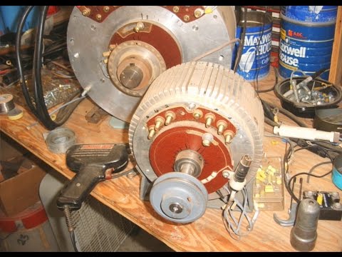
I was interested in the details of his controller as well as his "perm mag" motor, the combination of which has been claimed to be capable of achieving a COP>1, whereby I was specifically interested in the way he controlled the three phases in his motor. His Perm Mag motor itself is of a design that is very common today: a brushless DC motor with permanent magnets:
https://en.wikipedia.org/wiki/Brushl...electric_motor
Such motors can a/o be found in floppy drives, which would thus be ideal for experimentation with DIY 3-phase controllers:

Even the hall sensors Ron also worked with are included, the three chips that can be seen on the upper part of the motor.
When we look at Bedini's schoolgirl, the Tesla switch and Ron's perm mag motor, there's two things that stand out:
1) Some kind of "resonance" or oscillation;
2) Capturing BEMF.
In an article in Extraordinary Science (1994) abour Ron's work, we find an interesting detail:
http://www.tuks.nl/pdf/Reference_Mat...sue-4-1994.pdf
Now let's take a look at how brushless DC motors are typically controlled, the asymetric bridge converter:
https://en.wikipedia.org/wiki/Switch...ower_circuitry
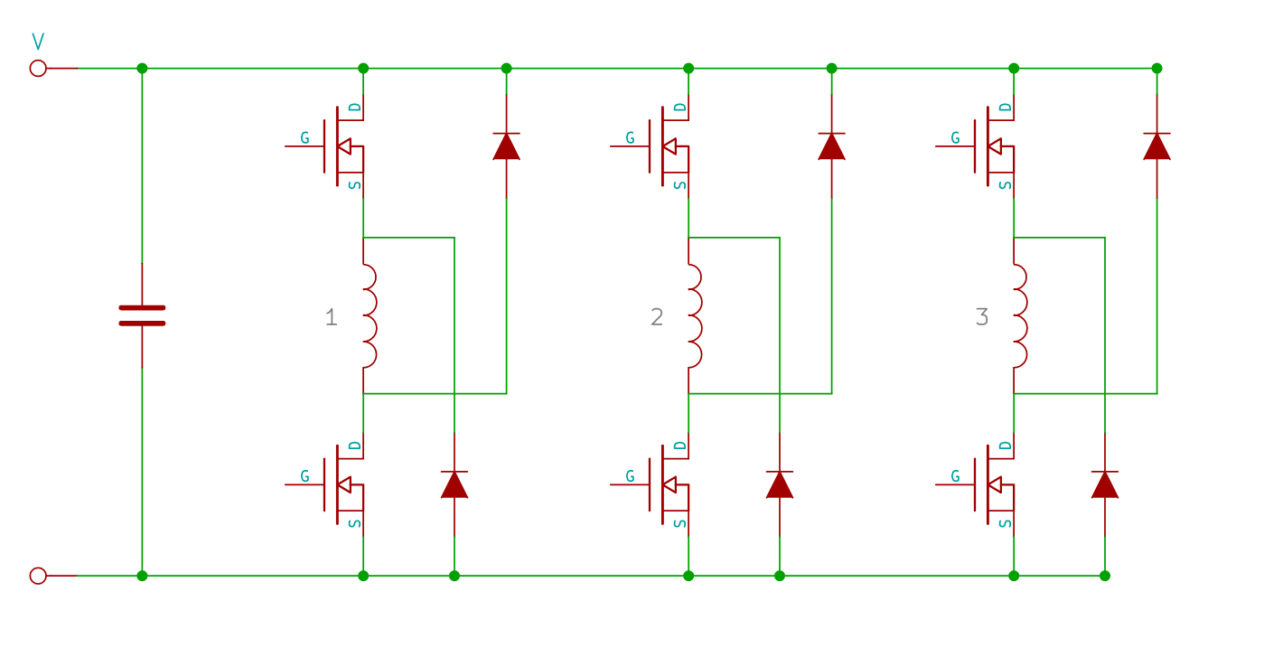
What is interesting is that this essentially the same circuit as Bedini uses, albeit for three rather than one coil or "phase", with the crucial difference that in this case both the high as well as the low side (of the coil) are being switched. This way, two recovery diodes can be used instead of one and thus the "loop can be closed" and the BEMF can be captured in the capacitor without shortcutting the coil.
What is also interesting is that with the use of a couple of diodes, we can make it so that a number of capacitors (or batteries) can be discharged in parallel, while being charged (by the BEMF) in series:
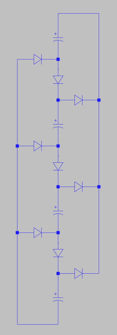
Note the similarity with (one half of) Ron's original Tesla switch, from the Extraordinary Science pdf linked above:

It is rather interesting to consider the amount of charge stored in two identical capacitors C charged to a voltage V. In series, the total capacitance C_s = C/2, while the total voltage V_s = 2*V. And since Q = C*V, in series we obtain a total charge of:
Q_s = C/2 * 2 * V = CV.
In parallel, the total capacitance C_p = 2C, while the total voltage V_p = V. So, in parallel, we obtain a total charge of:
Q_p = 2C * V = 2CV.
So, it seems that in order to charge two capacitors in parallel, one needs twice as much charge (= current * time) as one needs when charging in series. This is what makes that charging capacitors in series with a constant current goes faster than in parallel with the same current. And we can utilize this by discharging our capacitors in parallel when building up the magnetic field in our inductor, while switching them in series to capture the BEMF with the cap bank circuit shown above.
The advantage of the cap bank circuit is that the switching between series and parallel goes automatically and occurs at the moment the transistors are both switched off (at the same time). It seems that in various incarnations of the Brandt-Tesla switch, the switching between series and parallel is done differently, which might explain why these are hard to tune and only work at specific frequencies thus requiring "resonance".
Either way, I decided to run a few simulations with LTSpice (which can be freely downloaded). You can find the .asc files as well as the images above here:
http://www.tuks.nl/Spice/BEMF_Capture/
First, I simulated a conventional circuit with one coil ("phase"):
SR_Bridge.png
I plotted the current through the coil, the capacitor and the diode from the power supply as well as the voltage over the capacitor:
SR_Bridge_simulation.png
The green line is the current trough the coil and as we can see, it charges and discharges in about the same time this way. The light blue line is the voltage over the capacitor, which shows a sudden jump at the time the transistors are switched off, whereby the current through the cap rapidly reverses in direction.
Now the situation with a cap bank with two capacitors:
BEMF_Capture_2.png
And the result:
BEMF_Capture_2_Caps_Simulation.png
As we can see, now the coil discharges it's BEMF quite a lot faster, which improves further by adding more caps & diodes:
BEMF_Capture_4_Caps.png
And the result:
BEMF_Capture_4_Caps_Simulation.png
As we can see, this results in the coil discharging (it's BEMF) even faster.
Conclusion:
From the simulation results, it appears clear that when utilizing a cap bank with some diodes, it is possible to reduce the time needed to collapse a magnetic field in a coil. According to Ron, doing so should maximize the amount of recoverable energy and thus should provide your ticket to "overunity".
Of course, it remains to be seen whether or not this is actually true by experimentation. I intend to experiment with this myself, but may some of you are interested in experimenting with this as well. If you do, please do share your findings.
I have recently been looking into some of Ron Brandt's work of which quite a lot can be found here:
https://drive.google.com/open?id=0B7...Us0WlJISnlxX2c
His presentation on the 1995 Extraordinary Science conference can be found here:
I was interested in the details of his controller as well as his "perm mag" motor, the combination of which has been claimed to be capable of achieving a COP>1, whereby I was specifically interested in the way he controlled the three phases in his motor. His Perm Mag motor itself is of a design that is very common today: a brushless DC motor with permanent magnets:
https://en.wikipedia.org/wiki/Brushl...electric_motor
Such motors can a/o be found in floppy drives, which would thus be ideal for experimentation with DIY 3-phase controllers:
Even the hall sensors Ron also worked with are included, the three chips that can be seen on the upper part of the motor.
When we look at Bedini's schoolgirl, the Tesla switch and Ron's perm mag motor, there's two things that stand out:
1) Some kind of "resonance" or oscillation;
2) Capturing BEMF.
In an article in Extraordinary Science (1994) abour Ron's work, we find an interesting detail:
http://www.tuks.nl/pdf/Reference_Mat...sue-4-1994.pdf
He learned that in a magnetic field, the strength of the field and how fast it collapses determines the amount of energy that can be recovered. The faster the magnetic field collapses, (back EMF) the more energy can be recovered for reuse.
Now let's take a look at how brushless DC motors are typically controlled, the asymetric bridge converter:
https://en.wikipedia.org/wiki/Switch...ower_circuitry
What is interesting is that this essentially the same circuit as Bedini uses, albeit for three rather than one coil or "phase", with the crucial difference that in this case both the high as well as the low side (of the coil) are being switched. This way, two recovery diodes can be used instead of one and thus the "loop can be closed" and the BEMF can be captured in the capacitor without shortcutting the coil.
What is also interesting is that with the use of a couple of diodes, we can make it so that a number of capacitors (or batteries) can be discharged in parallel, while being charged (by the BEMF) in series:
Note the similarity with (one half of) Ron's original Tesla switch, from the Extraordinary Science pdf linked above:
It is rather interesting to consider the amount of charge stored in two identical capacitors C charged to a voltage V. In series, the total capacitance C_s = C/2, while the total voltage V_s = 2*V. And since Q = C*V, in series we obtain a total charge of:
Q_s = C/2 * 2 * V = CV.
In parallel, the total capacitance C_p = 2C, while the total voltage V_p = V. So, in parallel, we obtain a total charge of:
Q_p = 2C * V = 2CV.
So, it seems that in order to charge two capacitors in parallel, one needs twice as much charge (= current * time) as one needs when charging in series. This is what makes that charging capacitors in series with a constant current goes faster than in parallel with the same current. And we can utilize this by discharging our capacitors in parallel when building up the magnetic field in our inductor, while switching them in series to capture the BEMF with the cap bank circuit shown above.
The advantage of the cap bank circuit is that the switching between series and parallel goes automatically and occurs at the moment the transistors are both switched off (at the same time). It seems that in various incarnations of the Brandt-Tesla switch, the switching between series and parallel is done differently, which might explain why these are hard to tune and only work at specific frequencies thus requiring "resonance".
Either way, I decided to run a few simulations with LTSpice (which can be freely downloaded). You can find the .asc files as well as the images above here:
http://www.tuks.nl/Spice/BEMF_Capture/
First, I simulated a conventional circuit with one coil ("phase"):
SR_Bridge.png
I plotted the current through the coil, the capacitor and the diode from the power supply as well as the voltage over the capacitor:
SR_Bridge_simulation.png
The green line is the current trough the coil and as we can see, it charges and discharges in about the same time this way. The light blue line is the voltage over the capacitor, which shows a sudden jump at the time the transistors are switched off, whereby the current through the cap rapidly reverses in direction.
Now the situation with a cap bank with two capacitors:
BEMF_Capture_2.png
And the result:
BEMF_Capture_2_Caps_Simulation.png
As we can see, now the coil discharges it's BEMF quite a lot faster, which improves further by adding more caps & diodes:
BEMF_Capture_4_Caps.png
And the result:
BEMF_Capture_4_Caps_Simulation.png
As we can see, this results in the coil discharging (it's BEMF) even faster.
Conclusion:
From the simulation results, it appears clear that when utilizing a cap bank with some diodes, it is possible to reduce the time needed to collapse a magnetic field in a coil. According to Ron, doing so should maximize the amount of recoverable energy and thus should provide your ticket to "overunity".
Of course, it remains to be seen whether or not this is actually true by experimentation. I intend to experiment with this myself, but may some of you are interested in experimenting with this as well. If you do, please do share your findings.
Comment