Announcement

Collapse
No announcement yet.

Motionless Electromagnetic Generator / Holcomb CopyCat?

Collapse
X
 
  • Filter
  • Time
  • Show
Clear All
new posts

  • #16
    AI Smart Electromagnetic Generator | My Site (semp.or.kr)
    To make it "more fun", there are two documents on the website of Korean Research Institute the author of the development:

    Issuance of test results from KOLAS nationally accredited testing institutes: 90dcf3_c5427982bb984d19a4b03f6ba5ef96b5.pdf (semp.or.kr)

    KEPCO's official measurement report for 2020: 90dcf3_caade5f585bb4eccb3722c537f596486.pdf (semp.or.kr)

    index.php?action=dlattach;topic=3003.0;attach=124429;image.jpg

    Comment


    • #17
      Originally posted by Rakarskiy View Post
      AI Smart Electromagnetic Generator | My Site (semp.or.kr)
      To make it "more fun", there are two documents on the website of Korean Research Institute the author of the development:

      Issuance of test results from KOLAS nationally accredited testing institutes: 90dcf3_c5427982bb984d19a4b03f6ba5ef96b5.pdf (semp.or.kr)

      KEPCO's official measurement report for 2020: 90dcf3_caade5f585bb4eccb3722c537f596486.pdf (semp.or.kr)

      index.php?action=dlattach;topic=3003.0;attach=124429;image.jpg
      Thanks Rakarskiy,
      the first link bombs. The second appears, from the English portion, to be a certification from kepco, the instrument company, that the meter is calibrated at 10V and 1.0A, for 0, 60, 120 & 300Hz. For what its worth.

      From the note above the screenshot, it looks like the input was a DC source (battery?) pulsed with 1.3% : 98.7% duty cycle. I see no indication that the instrument could accurately measure that power signal. And having no output waveform, I have zero confidence in the output measurements with that instrument.

      IMO, no verification.
      bi

      ​​​​​​​

      Comment


      • #18
        Hi bistander !
        This device, according to the figure, measures DC current, (Current Strength and Effective Voltage). This DC current is probably pulsed (the frequency on the display indicates this possibility).
        All the device has recorded is the input/output power torque W=IU. But even these figures are impressive.

        I don't know how it works, but it's certainly not according to the algorithm in the patent application. They've hidden the technology. And the experts here are all stumped. https://www.overunityresearch.com/in...seen#msg109702
        Last edited by Rakarskiy; 01-06-2024, 10:07 AM.

        Comment


        • #19
          Originally posted by Rakarskiy View Post
          Hi bistander !
          This device, according to the figure, measures DC current, (Current Strength and Effective Voltage). This DC current is probably pulsed (the frequency on the display indicates this possibility).
          All the device has recorded is the input/output power torque W=IU. But even these figures are impressive.

          I don't know how it works, but it's certainly not according to the algorithm in the patent application. They've hidden the technology. And the experts here are all stumped. https://www.overunityresearch.com/in...seen#msg109702
          I'm not stumped. It doesn't work as claimed. So, false claim.
          bi

          Comment


          • #20
            I agree that the absolute proof of the reality of the work can only be a quantitative measurement in time of the received and produced energy. For example, Holcomb claimed a sevenfold exceedance capability, but on real sites no more than 2.5 times. Koreans had to install it on the object and show its performance in real conditions. In any case, what is stated in the patent is absurd. Perhaps UFOpolitics will prove the opposite in their technology

            Comment


            • #21
              An acquaintance of mine found something in a previous Korean patent.

              Below is an excerpt from patent KR10-1913746 B1:
              [0049] Figures 4A and 4B are schematic illustrations of the operation principle of the output unit 130 of a frequency and voltage controlled alternator according to one embodiment of the present invention.
              [0050] As shown in Fig. 4a, a direct current from the direct current source 110 is supplied to the first field winding 134 (forward excitation coil) via the IGBT IC PM (not shown), while no current is supplied to the second field winding 135 (reverse excitation coil), and N, S poles are formed on the magnetic pole 133. When current is applied to the second excitation winding 135 (reverse excitation coil) via the IGBT IC PM (not shown), no current is applied to the first excitation winding 134 (forward excitation coil) of the first winding, and poles S, N are formed on the magnetic pole 133.
              [0051] Thus, the magnetic field N, S and the magnetic field S, N are applied to the magnetic pole 133 through the first excitation winding 134 and the second excitation winding 135, forming an alternating magnetic field in the armature winding 136, ultimately generating an alternating voltage EMF therein.
              [0052] When current is applied to the first field winding 134 (forward winding) or the second field winding 135 (reverse winding), the windings in the other direction have already generated an electromotive force. The armature winding already has electromotive force, so the power output of unit 130 increases while the current from unit 110 remains the same
              [0053] Fig. 4b shows: the IPPT power (of block110) is applied to the first winding 134 for a first quarter (T) of the cycle time and then switched off. The IPPT power 110 is then applied to the second field winding 135 for the second half (T) to three quarters (T) of the cycle time and then disconnected.
              It can be seen that single-phase AC power is ultimately delivered through the armature winding 136. The power factor in Fig. 4b is illustrative and can, of course, be changed to a suitable power factor.

              P.S. Fig. 4a and Fig. 4b are taken from a PDF document in Korean and checked with the corresponding figures from this patent in two other languages - English and Chinese - as well as the text of the patent as a whole
              ___________
              I have been using this four-stroke system for a long time, but I have never had more than a СOP-1.4.
              Definitely the same four-stroke system that Alec used in his transformer US9620280B2 - Energy management system - Google Patents

              Comment


              • #22
                Good day friends!
                A bit about interesting comparisons;

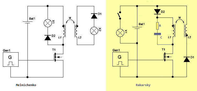
                Excerpt from the book "New Sources of Energy" by Alexander Frolov (inventor of Ф-machine, Ф-transformer), about Andrey Melnichenko's generator design:

                Quote:
                In 2010-2011, we discussed with him the successful tests of his generators organised at Moscow Technical University. At this stage, efficiencies of 150-200 % have been obtained, allowing the design of "advanced" battery-powered uninterruptible power supplies that do not require recharging from the mains. One of Melnichenko's schemes is shown in Fig.104.
                _104.png
                Figure 104.
                One of the circuits of the Melnichenko oscillator. Frequency adjustment or coil core adjustment is required. In general, it is the usual resonant mutual induction. However, the flux-coupling in this case is weak, so the effect of the induced current field of the second electromagnet on the primary source is negligible. The primary source produces a varying field, and the secondary source converts the fluctuations of the field energy. It can be said that the second electromagnet is more like a detector circuit or a "resonant receiver of aether fluctuations" than a transformer secondary circuit.

                The essence of this effect is that if you put next to an "open electromagnet" (whose core is not closed, for example, a rod or ferrite rod) another "open electromagnet", an electromotive force is induced in the winding of the second electromagnet, and some power can be extracted.


                If you draw my scheme of the inverse converter (link) with two windings of the transformer, the principle of operation of the secondary circuit EMF is identical. The question is that the smoothness of reduction of magnetic induction in the core(s) Andrew solved with an additional resistance Lamp X1. In my variant RC chain was used to minimise the reverse current in the primary circuit of the circuit and to increase the self-induction EMF in the window of the transformer with the secondary winding. The self induction EMF which started the process of operating the secondary circuit inductor from the maximum EMF value.


                This point, I was led to realise what to look for in the Figueras system, is when a smooth pulse of increasing current in the circuit, without changing the applied voltage to the control coil and a simultaneous procedure of generating generator type EMF in the secondary circuit.


                In my scheme and Melnichenko's, the Flyback converter system, which has TWO TACTS, is the working one. If we make a four-stroke system and somehow organise the control of the secondary circuit to avoid mutual induction for four cycles, it is quite possible to assume that the Korean generator works on forming the self-induction EMF of the primary circuit to add to the EMF of the generating circuit;

                The principle of addition of EMF generation and self-induction I suggested and described in my paper "electric field energy source"

                Quote:
                Taking into account the illumination by the electric field of the first winding, the formula would be as follows:
                I = ((Ew2 +(k*Ew1) - U) / (Rz + r)
                In blue is highlighted the very addition, Ew1 with a coefficient k, to which it is still not clear how to calculate this electric field of the inverse EMF of the primary winding w1, which is increased by the presence of the resistor R(10K)
                and the diode, or damper C;R in the shunt circuit. It is when there is voltage in the primary circuit that the secondary circuit has a current pulse and a large EMF with respect to the source (ballast capacitor) into which the charge pulse goes. Provided that there is also a change (reduction) in inductance (reduction of the secondary winding reactance), at the moment when the rotor/stator teeth open, the return pulse should be even more powerful.

                Last edited by Rakarskiy; 01-15-2024, 01:13 PM.

                Comment


                • #24
                  Hi Rakarskiy,
                  interesting document you have found. Thanks.

                  Have not attempted translation, yet. But looking at figures. The schematic shows unusual connection of gates of the power switching modules which I thought were IGBT's. It's been years since I have actively worked with such devices but I never saw a dual module with gate connected to funny diode as shown. Also gate drive method is perplexing. Unusual use of optocouplers driving gates to ground. Have you seen this done before?

                  From photos they posted of the power switches on those large heat sinks, it appears to be very crude power inverter design. Lots of parasitic inductance busswork and no snubbers. They must switch at low speed.
                  *
                  bi


                  Screenshot_20240116-061837-321.png


                  Screenshot_20240116-060735-896.png


                  ​​​​​ image_25351.png
                  Last edited by bistander; 01-16-2024, 04:45 PM. Reason: *removed comment on 2nd thought

                  Comment


                  • #25
                    Good time. bistander!
                    This is not a surprising connection system for me. I worked it out even earlier when making my own version of the Bedini motor. When disconnecting the upper key (transistor) the self-induction EMF will get the value of negative polarisation. Probably by this the transistor work is saved, but at me they burned as usual.
                    The fact that this electric field works on the secondary winding even any simulator considers.


                    Attached Files

                    Comment


                    • #26
                      Originally posted by bistander View Post

                      Have not attempted translation
                      This patent was found by an acquaintance of mine, to show that there can't be fabulous efficiency there. I agree with him no more than 2.0.

                      http://www.energeticforum.com/forum/...808#post512808

                      Comment


                      • #27
                        Originally posted by Rakarskiy View Post

                        This patent was found by an acquaintance of mine, to show that there can't be fabulous efficiency there. I agree with him no more than 2.0.

                        http://www.energeticforum.com/forum/...808#post512808
                        But never real proof or replication.
                        bi

                        Comment


                        • #28
                          To get at least 1 W*s excess in the quantitative energy balance, the self-propulsion balance with load (excitation, return and load) should be 3 W*s.
                          With the reverse power reading COP 1.4 -1.7 I have not achieved self-propulsion even on maintaining the battery at the original charge level.

                          Graph of the current oscillogram at the shunt resistor in front of the battery minus terminal.
                          2023-06-10_175603.jpg
                          The battery voltage is 12.9 V. The excitation time interval is 70%, the maximum current is 0.39 A (linearity of growth on the graph). Reverse pulse generation 30% (current waveform on the graph), maximum current 1.34 A. When recalculated taking into account the pulse duration, the efficiency was approximately COP -1.4, which is not enough to maintain the initial battery charge level, the battery loses charge very, very slowly.

                          The scheme according to which the experiment was carried out above by analogy with Melnichenko.

                          Thus, it is not clear what technology is used on the magnetic system of Koreans, but obviously not the one they tell about.
                          I have guesses and if they are confirmed Koreans are not the first and we can even make a small scandal.
                          Last edited by Rakarskiy; 01-17-2024, 07:43 AM.

                          Comment

                          Working...
                          X