Announcement

Collapse
No announcement yet.

Resonance- nice & simple

Collapse
X
 
  • Filter
  • Time
  • Show
Clear All
new posts

  • #31
    Re: Debunked

    Yes can probatly be, that it dont works.
    I made a fast Experiment today, where i lay 2 same wounded Coils
    with same wire lenght beside eachother, connected over a Rectifier to a 4700 Cap and a Led.
    The Coils are actually from a weird medicinal apparatus so they should be pretty equal.
    Wires been some bigger actually about#26 AWG/0,3mm. This Coils at the Vid may have #30/0,1mm

    I know, that this Rectifiers are pretty crap, Made in India, there are a lot looses at them.
    I fired the Caps with 6V up, and anyhow the Leds did take a While, till they did go out, maybe 5 Minutes, where they still did dim.

    I got somewhere such a Shakelight, to look what circuit they use there,
    but anyhow i cant find it.
    Dont know, if they still have more Resistors in there, or only rectifiy it over one End.

    Its anyhow a interesting Idea, because W. Barbat had a similar Patent on something like this.
    William Barbat: Self-Sustaining Electrical Generator; United States Patent Application # 0070007844
    But just like this, it did not really work for me.
    Theorizer are like High Voltage. A lot hot Air with no Power behind but they are the dead of applied Work and Ideas.

    Comment


    • #32
      Thanks guys, i had a feeling it was " too good to be true"

      Comment


      • #33
        Hi folks, aromaz said,
        Debunked.

        This gent is a fake; so are most (if not all) his attempts to draw attention.
        How do you know this to be a fake, have you tried to replicate it as he describes what he used.
        peace love light
        Tyson

        Comment


        • #34
          Originally posted by rave154 View Post
          Hi all,

          just came across this by accident ( as usual )..... dont quite know what to make of it...neither does the guy in the video, he seems as puzzled by it..

          i have placed this in this "resonance" thread because.....well...im not sure really..

          YouTube - FREE ENERGY FROM RESONANCE, I THINK! WHO KNOWS WHY!

          hopefully somebody out there has two or more of these shake-lights and can have a play with them.

          David. D
          Its a FAKE China Shake Light . heres one here . It has a one layer copper wire to look like a coil and the wires are not attached to anything and the "magnet is just a piece of shiny metal that wont attract a papercilp . see the two lithium batteries I got these years ago and they still work .That guy is a scammer . If you are buying a shake light check the body with a piece of steel and see if it stick to the side first . Geezz.. Also if you notice in his video he waves a magnet over it and the piece of metal don't move Listening to him makes my stomach turn
          fusionchip
          Attached Files
          Last edited by fusionchip; 12-29-2009, 03:14 AM. Reason: edit

          Comment


          • #35
            Hi folks, thanks for the information fusionchip, however he does claim his shake lights use capacitors and so an attempt at replicating must be made at the least to know for sure, i think. I don't have any shake lights to test with, though maybe trying to emulate the configuration would be good. I am aware based on experiment how the 555 timer goes into self oscillation, so this could be occurring in the shake light circuitry to somehow create a self regenerating oscillator, if it indeed works as claimed.
            peace love light
            Tyson

            edit: it could be possible he thinks their capacitors because the batteries are practically dead and so any shaking of the light will show a discharge curve somewhat like a cap. after all a battery is pretty much a large capacitor. Just a few thoughts.
            Last edited by SkyWatcher; 12-29-2009, 05:44 AM.

            Comment


            • #36
              Guys, the only coclusion form my involvement in the field so far, is that if any OU devie is to be made, it would be far from simple or will employ extraordinary materials arranged in peculiar manners.

              Again, assuming this faker had really found an "OU" lead, my first assumption will be that the surplus energy is far more possible to come from a near malfunctioning electronic device charging his coils somehow, or even i could believed a peculiar energy vortex could have been formated in his area and powered his device LOL, rather than his noob two coil arrangement exploiting ZPE.

              I think most of us, are well educated so far, the hard way, so as to perceive what has any potential in it and what does not.

              Baroutologos

              Comment


              • #37
                Bare in mind guys, that the guy might NOT KNOW that he has dodgy shake-lights....and may simply be mistaken & fooled into thinking hes generating power etc...im sure weve all been in the position where we think " IVE DONE IT !!! ".......only to find out we have mistaken some thing here or there...and what we thought was happening isnt actually taking place...

                having said all of that....he does appear to selling quite a lot of stuff & plans etc on his site.....so....hmmmm

                Comment


                • #38
                  Total scammer!

                  That guy is a total fake!

                  I ordered his free energy coil and free energy plans
                  about a year and a half ago and never received anything!

                  He made some lame excuses for a couple of months
                  until I got tired of beating a dead horse.

                  Guess he needed my money more than I did

                  Comment


                  • #39
                    Hi,

                    going back to the orignal post in this thread,

                    AC is input into the LC circuit, frequency is adjusted to the resonant frequency until apparently "no current" is flowing in the said circuit as evidenced via the bulb dimming almost to completely going out.

                    Having said that, the voltage & current are perhaps 90-degrees out of phase.

                    however, while all of this is going on, the bulb in line with the other circuit lights brightly.

                    What can we say/deduce with reasonable certainty about the above setup?

                    Comment


                    • #40
                      If you are talking about the resonance experiment...

                      Originally posted by rave154 View Post
                      Hi,

                      going back to the orignal post in this thread,

                      AC is input into the LC circuit, frequency is adjusted to the resonant frequency until apparently "no current" is flowing in the said circuit as evidenced via the bulb dimming almost to completely going out.

                      Having said that, the voltage & current are perhaps 90-degrees out of phase.

                      however, while all of this is going on, the bulb in line with the other circuit lights brightly.

                      What can we say/deduce with reasonable certainty about the above setup?
                      The original posters demo video shows what we are facing here. One thing that has not been looked into much is the effect of frequency on the light bulb itself. At 10 volts the frequency as it is being adjusted will effect the light bulb in the same way as a transformer. The light bulb has a coil usually as the element and this has a resonance as well. When the light bulb's element hits it's resonance frequency it passes the current without converting the current into light and heat. This is a sheath like covering over the structure of the coil of the element. Resonance allows current to flow over the coil as if the coil isn't there at all. In fact if the coil is of sufficient size or mass it can pick up more energy from it's environment as it traverses this sheath of super conducting field, much like any process we look at in fluid dynamics.

                      An well established example of this effect would be the Dyson fan. It turns out that Tesla's experiments with odd shaped coils, conical, geometry is very key to the compression or decompression of this sheath as it changes geometric shape while traveling over the coil. Tesla did the experiment just after seeing that when he used these huge pulses of pure voltage, that most of his coils in the shop visually showed the sheath and whistled like a huge amount of air was flowing around the coils. This got him to start experimenting with conical coils and the effect of compression of this sheath and the subsequent amplification of the potential or the voltage. This amplification was actually more environmental charges getting dragged along and added to the amplification of the voltage. So compression as in a fluid causes more pressure and in the case of voltage a higher potential as well.

                      I think in order to use this technology we must break away from symmetrical coils and start looking to compression and decompression of the potential through non symmetrical coils.

                      It should be possible to create energy valves that once kick started constantly produce a compression/pickup of potential much like a vortex gets created in a tub of water that has an open drain. The thing about this process is that it would not depend on the availability of the source because that source is very dense around our planet.

                      This brings me to the medium that this resonance uses to propagate on. Tesla touched on it a bit if you read his papers. The medium is just the vehicle of the energy. But that medium has to be organized by something. Lets call it particle omega. How do we know it is organized? Well all discharges have an organization to it. It has a form and the basic shape or geometric pattern of this particle omega is the defining organization. It rears it's head in anything we look at in nature. It is very very old and is the superconductor we have been looking for. It is so plentiful around our planet that it can support billions of lives and an eternity of matter.

                      Just like Rodin figured out it is highly subjective to geometry of matter to interact with it. If you obey the geometry and unlock the channels then perfect transfers can happen in an instant of time. Let me explain.

                      Take the dotted line example for instance.

                      .................................................. ............

                      That line has organization to it and this line has nothing organized:

                      Please omit the dashes they are free space:

                      .--.----.----.--.-.-.----..--.---.---..-.--..-.-.-A
                      -..-.....-.....-...-.-.-.....--..-....-....--.-..--.-.-.B

                      Line B is the target line that we want all the dots to line up to. Line a is the displaced network that is around our planet. The network is there because of the matter of the planet and they radiate out of the planets core. If we wanted to enact a change on the lines how far would each dot have to move to align to line b? One space right? How fast do you think that would be? No matter how long the line is it would take an instant for 1 million miles to align to line b's position because it is not far for line a: dots to travel to line b:'s position.

                      The most curious effect comes when they do align. It creates a perfect path and then allows the environment to flow along with it. Sucking in more potential because the network grows like the veins in a leaf. Growth takes time but the initial organization happens in an instant. Growth is just more particle omega's joining in or being carried in with the vacuum the flow creates.

                      Now don't get me wrong not all of the network is established. Some of this network is mobile and very dynamic. In fact I think the most viable proof of this is that water is so needed for life. Water is a super condensate of this network. It is the network buried in matter with very little energy but what it needs to stay together or congealed. Besides the environments contribution this congealed network has little energy of it's own yet it is the best super conductor and why it is so phase transient, meaning changes form from ice to water to steam so easily. If this is the case then the crystallization of water when it freezes has to rely on something to get that kind of organization from this fluid when we extract what energy it does have through freezing the water.

                      I know this is long winded but I though maybe we should talk about,in depth, what we are using when we energize a coil.

                      Comment


                      • #41
                        Hey guys,

                        good work on the resonance front. Here is an interesting concept I designed to take advantage of resonance within a motor. This is its simplest embodiment, but the concept is the useful golden nugget. I will only hijack the thread for a moment ,because I think what to do with resonance is where most people get stuck....like "how do I apply it to a motor?" I call it my peg motor, or universe engine.

                        this is the first post I made regarding the problem with LC's within a motor and sets up the dilemma.

                        I rarely, post..... and Personally im no motor builder, but I think something is being missed by most on this thread.

                        I have read several people ask about generators, however the motor in its present incarnation is not all it could be, this is most likely to get the home experimenter comfortable with the basics before moving on.

                        Take for example an AC generator, with field windings, and permanent magnets on the rotor. The field windings could easily be wound into an LC circuit making the motor supposedly run on reactive power. However, what is not immediately obvious is that the rotation of the rotor will impart upon the filed windings an EMF from the magnets directly related to its rotational speed and the number of poles on the rotor. This counter emf per lenz law will create a frequency within the LC at varying speeds (depending on rev-up, down, loading, etc) which will not match its resonant frequency, hence hindering the resonant rise, Q, and overal efficiency of the motor. However if you had a lenz less motor, the result would be a rotation caused by the driving circuit independent of a generated EMF due to the rotation of the rotor. Such a motor could be run by a resonant circuit, returning all power given to it back to the source, in this case, the source might locally constitute a capacitor with an impedance matching the drive coils for a particular frequency. This tank circuit would be allowed to oscillate freely, without having to worry about any stray emf frequencies created by the rotor.

                        This cannot be easily applied in its present form to the current motor as it stands. The rotation of the current model is dependent on the position of the rotor with respect to the pole projections of the stator. This means that frequency of operation within the drive coils is dependent on rotor speed, meaning it too is tied down to rev-ups, downs, variable loading etc. In order to reach a reactive state at a particular frequency, the rotor would have to spin at a very specific speed.

                        Also noted, is that the inductive properties of this motor change constantly! which is terrible for such a design. Hence the fact that it is a variable reluctance motor. This property too is detrimental to reactive conditions.

                        BUT! it has one of the problems solved, and clever geometries and tricks can solve other problems. Such as reactive rotors (Tesla has patented them) constant reluctance rotors (would need a simulated rotating field, where poles switch at a phase less than 180 degrees) and other ideas come to mind.

                        What you were all given is gold, but it is far from where it could be, and I get a sneaking suspicion that the only thing that is holding Dr Lindeman back from advancing ideas publicly at this point is the overall comprehension, i.e. no point in leaving people behind at this point.

                        Get clever with similar concepts and you can apply it all to solid state as well, leaving behind the need for kinetic power supplies.
                        (like I said im no motor builder........ )

                        And thank you Dr. Lindeman for your work teaching, and taking the time help people out. I have given you an unfair shake in the past.
                        And here is his reply where he affirms what I have said about a constant reluctance motor being able to run on reactive power such as an LC.

                        Thank you for your kind and insightful remarks. With regard to your post about the Jim Murray Generator design, I have known Jim Murray for 20 years and we published this patent in Borderland Magazine back in the 1980's. All of the people I worked with in Santa Barbara, including Mike Knox, Eric Dollard, and Chris Carson, met with Jim Murray a number of times after I moved away in 1992. Jim and Eric subsequently solved the solid-state method for converting reactive power back to real power using Jim's methods applied to Eric's FOUR QUADRANT THEORY of electric waves. All of these things you mention have already been accomplished.

                        While Jim has built working models of this generator, getting all of the electrical and physical resonances in phase is tricky. The machine does NOT exhibit drag free operation until these conditions are all balanced and synchronized. Still and all, it does PROVE that electric motors and generators are NOT converting mechanical energy into electrical energy. The First Law of Thermodynamics does not apply to properly built motors and generators. For those of us who know the truth, this is not a problem.

                        As you have correctly stated, there is little purpose showing more precise theory in a forum like this when the model building difficulty only gets worse than what has already been shown. I will tell you plainly, however, that the CONSTANT RELUCTANCE MOTOR is the ticket and special geometries are the method of accomplishment. When the reluctance does not change at all during the power stroke, then the inductance of the circuit remains relatively constant as well. This allows for the design of a true, constant speed, synchronous motor that produces maximum mechanical power on 95% reactive power and about 5% real power. This allows a COP=20 operation as technically feasible.
                        the next post shows the concept

                        Comment


                        • #42
                          ]The concept is loosely modeled after my understanding of our solar system.


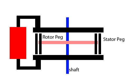
                          This is a birds eye view of the rotor (with four poles) and rotor (with four poles).

                          The poles are simply ferromagnetic cylinders much like you get with ferrite Antenna found in old AM radios. The only job of the rotor is to spin these poles into and out of alignment with the stator poles.

                          Now imagine that above this setup, (and below) we place a ferromagnetic toroids which covers all the poles simultaneously.

                          Here the toroid is shown semi transparent so you can view the setup.

                          http://i210.photobucket.com/albums/b...3/Picture1.jpg

                          Connecting the top and bottom toroid is an inductor.


                          Inductor shown in red. As you can see, the pegs of the rotor and stator complete the magnetic path of the inductor.

                          The same polarity will be induced on both the stator and rotor pegs.

                          Fact: when two bar magnets are aligned with poles in the same orientation (such as the rotor and stator) they will repel. Hence, when the rotor pegs, and the stator pegs are aligned, they want to move apart. Obviously they will move till the rotor pegs are directly inbetween two stator pegs, and then there will be equal repulsion from both sides. The firing circuit of the solenoid needs to take this into account. This is the mechanism through which rotation is induced..

                          What is so special about this design? It nearly constant reluctance and inductance. Imagine hooking up an inductance meter to the solenoid. Now spin the rotor, will the inductance change much? Through out the full rotation, there is always the same amount of ferromagnetic material in the magnetic path, hence very little change. Also, rotation will cause NO EMF, you can spin this guy all you want, and you will never get an iota of power out the inductor, like in conventional motor systems.

                          The constant inductance and reluctance mean up to 95 percent of the input to the inductor can be recovered (unlike peters motor, and conventional motors)

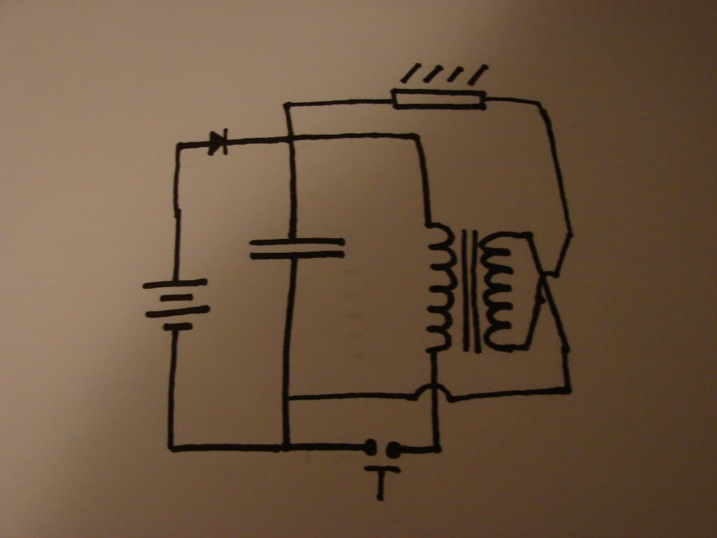
                          If I were to use a recovery circuit, it would probably look something like this....


                          Optically switched, this can charge the inductor at the correct moment, causing rotation, then recover the pulse for the next pulse. This solves all the problems Peters motor had. It can act reactively at all speeds.

                          I put the answer plain as day in the first few pages of that thread, I just left out how to do it. Other ways are possible as well, the key ingredient is

                          Constant reluctance, constant inductance,

                          Comment


                          • #43
                            One can see how this design eliminates the problems with stray EMF's causing degradation of the Q within a tank circuit, this is how it all works!

                            Comment


                            • #44
                              The theory that explains how electron motion energy is brought-in at resonance

                              The theory behind your resonance demonstration

                              Dear Armagdn03,

                              I believe that you may be interested in a theory behind your resonance demonstration set up. This theory essentially states that:

                              1. Orbiting electrons act as magnetic dipoles. These electrons have energy related to their motions.
                              2. Normally, such dipoles point in random directions and show no net magnetic effects.
                              3. If suitable electric or magnetic pulsing is applied, the random order may be changed into a pulsing order. The pulsing order will bring-in the electron motion energy into the system.
                              4. If the supplied energy is X and the bring-in energy is Y, the total effective Input energy to the system is X+Y. If there were no energy loss, the Output Energy can be X+Y. The COP (Output Energy/Supplied Input Energy) can be much greater than 1.
                              5. Please read the detailed descriptions in http://www.energeticforum.com/renewa...gy-theory.html

                              You do not need to explain why your resonance set up can have COP > 1 any more. You can use Aaron’s terms – you use an OPEN system in non-equilibrium thermodynamics. Or use my terms – the LCR resonance conditions enable the exciting forces to continuously bring-in electron motion energy into the system. The analogy is the simple swing. If you push it at the right frequency, the amplitude of the swing will be much higher. The forces will not hinder or cancel out each other.

                              If you are interested, I can produce the circuit diagram to measure the Input and Output Power and Energy of your resonance set up. The result should clearly demonstrate that COP > 1.

                              May God guide us all. Amen

                              Comment


                              • #45
                                great posts guys

                                arm,

                                i have a bi-filar coil, basically a spool wound with equal lengths of 24SWG & 26SWG until the spool is full....even though the two wires are of different gauges...would i be able to use this along with the appropriate capacitors...to re-create your original video?

                                Comment

                                Working...
                                X