Announcement

Collapse
No announcement yet.

Joulethief SEC exciter and variants

Collapse
X
 
  • Filter
  • Time
  • Show
Clear All
new posts

  • The tubes themselves need no rectification though, but it does depend on the application for sure and safety within all experiments
    For complete wireless you just bring one near to the tower and it will light, then draw it away to whatever range the tower can support (when not using matched resonant towers).
    A 1 wire system needs only to connect to the top of the tower, the unconnected end of the secondary. Then run that wire to all terminals on the fluoro.

    One thing i've always found is that common plastic cased FWBR's are highly inferior within our operating conditions, compared to little 1N4148's. Examples would be - GBU6D, KBL08, D3SB60.
    Interestingly, i've encountered many PC monitors and other circuits where 1N5408's are used, with tiny ferrite rings around the bases of each ones legs.
    1N4148's have been far and away the best performers for own experiments. Best rectification circuits have normally been comprised of a 30ish gauge 12 turn coil, 4x 1N4148 diodes as a bridge rectifier and a 10uF 16V cap across the output. That system on a 12V Slayer circuit is good for approx 4V at up to 500mA.
    One particular success some time ago saw amazing results with charging a cellphone to a far range...that used Zener diodes of whose spec I have no idea. Everything of mine is salvaged and recycled.
    Here's that vid:
    ‪The future of phone charging - extra‬‏ - YouTube
    Another method was recently suggested by jonnydavro (video on his YouTube channel) where a small signal transistor with a small aerial wire to it's Base is used, plus a 330uF 16V cap or so across the load.
    Straight cap charging with very high potentials has been achieved most easily by use of a simple AV plug and parallel connecting several high capacity caps, such as 220uF 400V. They will charge from the output of a similar tower some inches away and produce voltages up to the lowest rated if different types are used. The result, when shorted, are huge discharge sparks after a 1 minute charge time.

    Comment


    • Originally posted by xee2 View Post
      If you are lighting a fluorescent tube, then the voltage is over 400 volts (probably much higher). You should use at least 1000 volt diodes (1N4007).
      As I said, these are waaaay to slow!

      However, the voltage should not become very high, because what I am aiming for is to get current antinodes at the outer terminals of the coil, which would mean we would get voltage nodes at the terminals, since voltage and current are 90 degrees out of phase in a standing wave, as I posted here:

      Originally posted by lamare View Post
      Since Tesla wanted to drive a current into the Earth, he needed some reservoir to temporary store the electrons he wanted to juggle back and forth into the Earth, and that is the main purpose of the top sphere. It is a capacitive load, which keeps the top of the coil at a relatively fixed potential, and therefore the standing wave will show a voltage node and hence a current antinode at the top, since "current" and "voltage" have a phase difference of 90 degrees in standing electro-magnetic waves:

      See: Standing wave - Wikipedia, the free encyclopedia :

      The effect is a series of nodes (zero displacement) and anti-nodes (maximum displacement) at fixed points along the transmission line.
      Also see: Standing-waves

      The standing waves of voltage and current appear together. Observe that one is maximum when the other is minimum. The current and voltage standing waves are one-quarter cycle, or 90 degrees, out of phase with one another.
      So far, so good.

      Now what I wanted to illustrate with this practical example is that you can get a gain of energy using higher order resonances, and that it is also possible to get a while load train into one single resonance mode, as I mentioned in my reply quoted above.

      Note that Puharich used the energy out of the higher-order resonating coils directly (as Kapanadze does in his Kapagen device), while Tesla transformed it down using a pancake transformer.
      Let's take a look back at the basic design:


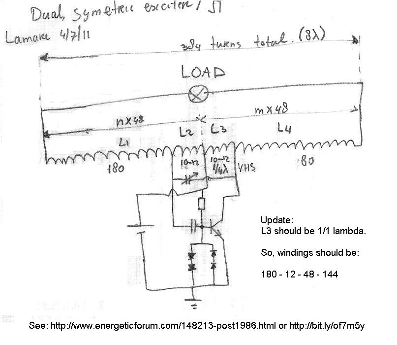
      The idea is that since the center tap is connected to a fixed voltage, there cannot be a voltage antinode there, so there must be a current antinode at the center tap. Since there is supposed to be 1/4 wavelength between the center tap and both the feedback and activation taps, these should be at voltage nodes.

      Update: feedback should be at 1/4, activation at 4/4. See post below.

      The end terminals should be a whole number of full wavelengths away from the center tap and should therefore also be at current antinodes c.q. voltage nodes.

      Now of course, when you let the outer terminals float, no current can flow out, so the standing wave will settle itself at a different wavelength and corresponding frequency, such that you do get a voltage antinode at the terminals and you can light a fluorescent with it.

      In my case, the natural resonance frequency is supposed to be around 1 MHz, since that is what Slayer said his coil oscillated on and IIRC that is also what I got with the previous incarnation of my coil when I replicated Slayers. Now it turns out to resonate at about 5 MHz, "measured" from the scope, so not very accurate. It could be anything between, say, 4.5 and 5.5 Mhz.


      So, what is supposed to happen when I attach a proper diode bridge, is that the outer terminals of the coils are at a more or less fixed potential in terms of high frequency response. That should force a voltage node to be present at the terminals, which should go along with a current antinode, and therefore we should have pretty low voltages along with a reasonable current in the order of a few 100's of milli-amps.

      You can find a datasheet for the 1n4148 here:
      http://www.nxp.com/documents/data_sh...148_1N4448.pdf

      According to this, it should be capable of handling 200 mA continuously and up to 450 mA "repetitive peak".

      If the 1N4148 does not hold it, high speed Schottky diodes like the 1N5817-1N5819 may be a good option:
      http://www.vishay.com/docs/94614/1n5819.pdf
      http://www.datasheetcatalog.org/data...es/ds23001.pdf

      Other ones:
      Schottky Rectifiers/Diodes * Small Signal and Power Schottky Rectifiers
      Last edited by lamare; 07-19-2011, 05:58 PM. Reason: oops. mixed up nodes and antinodes.

      Comment


      • I see your plan more clearly now too
        Btw, OOPS..meant to say Schottky not Zener above in my last reply.

        Comment


        • The MUR805, MUR810, MUR815, MUR820, MUR840, MUR860, MURF860 may also be interesting:

          http://www.onsemi.com/pub_link/Collateral/MUR820-D.PDF

          ULTRAFAST RECTIFIERS 8.0 AMPERES, 50−600 VOLTS
          The MUR820 is not too expensive (EUR 1,45 a piece at Conrad) and has a max recovery time of 25 ns, so it should go up to something like 1/(2*25e-9) = 40 MHz or so. (*)

          And here is a nice selection tol for ST diodes:
          Ultrafast Rectifiers - STMicroelectronics


          (*) This is just a guesstimate based on the recovery time, I don't really know if it is "allowed" to calculate it like this...

          Comment


          • Originally posted by Slider2732 View Post
            Another method was recently suggested by jonnydavro (video on his YouTube channel) where a small signal transistor with a small aerial wire to it's Base is used, plus a 330uF 16V cap or so across the load.
            Straight cap charging with very high potentials has been achieved most easily by use of a simple AV plug and parallel connecting several high capacity caps, such as 220uF 400V. They will charge from the output of a similar tower some inches away and produce voltages up to the lowest rated if different types are used. The result, when shorted, are huge discharge sparks after a 1 minute charge time.
            When you just connect the base of the transistor to the collector, you get a so-called "diode-connected transistor", which means: a transistor acting as diode. This is often used in integrated circuits and amplifiers when you want a current-mirror circuit, because you want both pairs of the mirrors to match as closely as possible:
            http://www2.ece.ohio-state.edu/~pavl...tor_basics.pdf

            In the laboratory, a “diode-connected” transistor (i.e., shorted base and collector) may match the base–emitter characteristics of another transistor better than a diode.
            The left pnp transistor is “diode-connected,” which means that its collector and base are shorted together.

            Comment


            • Looks like I have to rewind my coil..

              Looks like I have to rewind my coil again :

              Transistor Tutorial, Part 7: Oscillators
              Figure 6 illustrates the Hartley Oscillator, which is a variation of the tuned-collector oscillator that was shown in Fig. 5. This oscillator is recognizable by the tapped coil in its tuned resonant circuit. Oscillation of the Hartley oscillator circuit depends on phase-splitting autotransformer action of the tapped coil in the tuned resonant circuit.

              The tap is located on load inductor L1 about 20% of the way down from its top so that about 1/5 of the turns are above the tap and 4/5 are below. The positive power supply is connected to the tap to obtain the necessary autotransformer action.

              The signal voltage across the top of L1 is 180° out-of-phase with he signal voltage across its lower end, which is connected to the collector of Q1. The signal from the top of the coil is coupled to the base (input) of Q1 through isolating capacitor C2. The oscillator will oscillate at a center frequency determined by its LC product.
              Of course!

              The transistor is a device that draws current from the coil, so it has to be attached to a current anti-node. Since the central tap is at a more or less fixed voltage and therefore at voltage node and therefore at a current anti-node, we need to put the tap for the transistor at a full wavelength away from the central tap. The feedback to the transistor goes to the base and draws almost no current, so that should be at 1/4 wavelength from the central tap.


              So, I should have wound my coil like this:

              180 - 12 - 48 - 144

              So, one step further. One day all the bugs are out

              Update: I found this schematic and thus my error while looking for how they normally make Hartley oscillators, because with the current amplifier design, you get a very high amplification, which is what gives you the spikes. Now these are benefitial if your goal is to light a fluorescent wirelessly, because it radiates very nicely that way. As an illustation: I found out that if I wanted to play music while experimenting, I'd better go for some old tapes I have lying around in my shop, cause the radio ain't much of a pleasure to listen too, even at FM at around 100 MHz...

              So, if you goal is to try and come up with a design such that you may hope for closing the loop and make it self-running, the one thing you don't want to do is to radiate all the energy you have collected with your coil from the medium away into space. And therefore, for this exercise you want a nice smooth sine-wave and therefore an amplifier section with an amplification that is just enough to keep the oscillation going, but not such a high amplification that gives you these spikes and accompaning HF radiation....

              So, if you want to aim for trying to close the loop and make a self-runner, then you should base your circuit on the design above and not on the high-bandwidth stuff commonly used in JT/SEC circuits, IMHO.
              Last edited by lamare; 07-19-2011, 06:23 PM.

              Comment


              • Or, if you want to direct energies to an emission point ?
                See, that's where i'm at. I would like to create a system that generates the HV, but doesn't throw it 360 degrees around, hitting walls, going out through windows etc. Mostly, because such a system runs a lot like simple induction...the power is at a focal point of the top of the tower, not anywhere else.
                Ideally, such a thing would run within a radio controlled car/plane/heli/boat transmitter....the aerial becomes the directing guide, perhaps a different way of thinking about such a system. However, it's just like conventional radio.
                After that, a way of making such a wave disperse slightly, to a known angle, all calculated and that's where I know your maths skills are far superior to mine !
                As you say, lighting tubes at any point with a tower emissions based system is one thing, directing the energies is quite another.
                It was noted while tuning things up to light the 4ft tubes the other day, that while the single wire worked, I had a wireless field of no use and of wasted power for the goal of the experiment.

                I'd thought that a similar system to Wardenclyffe would be the route. Shake the ground, vibrate the air, recombine at a distance. I now foresee a few Hartley oscillator experiments

                Comment


                • Lamar, this is one I've played with to bring the current node to the outer coil ends. The earth ground will enhance the current in the system.
                  Last edited by dragon; 05-15-2012, 03:54 AM.

                  Comment


                  • Wardenclyffe was NOT SUPPOSED TO RADIATE!

                    Originally posted by Slider2732 View Post
                    I'd thought that a similar system to Wardenclyffe would be the route. Shake the ground, vibrate the air, recombine at a distance. I now foresee a few Hartley oscillator experiments
                    Don't make the mistake to assume the Wardenclyffe tower was supposed to radiate! It wasn't!!!!!

                    See my earlier posts at the Tesla Wireless thread:

                    Originally posted by lamare View Post

                    <snip>

                    Let's first first go to this excellent article on Tesla's Wireless system here which describes the history of Tesla's inventions that led to his Wireless idea very good:
                    http://www.andre-waser.ch/Publicatio...essSystems.pdf
                    (Copy here: http://www.tuks.nl/pdf/Reference_Mat...essSystems.pdf )

                    <snip>

                    On the first glance to the series of figure 2 to 4 one supposes that the energy transmission finally occurs through the air by the means of an increasing electric conductivity of the upper atmosphere. Actually TESLA[24],[25] has written in his first patents that this is the case. But with a closer look at his drawings there can be recognized that all his circuits has – beneath the high voltage transformers – an other common thing: the ground connection. In later publications TESLA[32],[36],[32] has mentioned explicitly that the really conductor of the power transmission is the Earth itself. The Earth acts like a giant reservoir for electrical charges which can be set into oscillation by his powerful equipment. Is now a very sensitive resonant circuit (receiver) placed on an other place on Earth, which is tuned to the transmitter‘s frequency, then the receiver couples to this oscillations and gains its signals due to resonance.
                    The force of an oscillating HERTZ dipole on a stationary charge is well known. This can also be described as a sum of forces between relatively resting, moving and accelerating charges as the author[45] has shown for the case of large distances to the HERTZ dipole. A transmission of electrical energy from one point to an other is certainly possible with a HERTZ dipole, too. But with increasing distance r form the transmitter the energy density diminishes rapidly. This law of distance can be undergone when instead of air under normal pressure a conducting medium (electrical wire) is used. An almost frictionless transmission of electrical energy between two points on Earth without wires only can be done by using some sort of a ‘connecting wire’, a voltage or current source and a load. This connecting wire is the Earth. The voltage or current source is the transmitter and the receiver is the load.
                    The elevated terminals D and D‘ function as a charge reservoir (electric capacitor), butthey do not act as the transmitting terminal itself, whereas the energy is given off to the air. [...] TESLA has operated the Earth as a ball capacitor. The transmitter “pumps” with a frequency between 20...250kHz[24],[32] electrons between the Earth and the elevated terminal back and fourth. To minimize the HERTZ radiation losses this frequency has to be as low as possible, as TESLA has mentioned explicitly. To achieve an optimal effect it is necessary to use high voltages.
                    Tesla illustrated this himself in an article "THE TRANSMISSION OF ELECTRICAL ENERGY WITHOUT WIRES" on March 5, 1904, which you can find at:
                    Transmission of Electrical Energy Without Wires

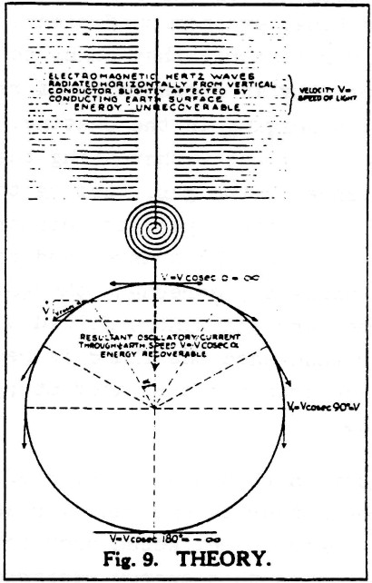
                    He used the following illustration to show the difference between electromagnetic radiation (either "Herzian" or longitudinal, btw):

                    The text in the upper part of the picture reads:
                    Electromagnetic Hertz waves radiated horiontally from vertical conductor, slightly affected by conducting Earth surface.
                    ENERGY UNRECOVERABLE
                    Now why is this so important? Because no matter what kind of waves are transmitted from the vertical conductor, with or without a sphere on top, the energy radiates away in all directions and is therefore lost for all but a very small fraction!

                    This same picture is also printed in Eric Dollard's book, with the following comment:
                    Tuks DrippingPedia : Theory Of Wireless Power

                    It can therefore be seen that while the transmission of transverse waves involves the spraying of energy, with its consequent square law diminishment of energy density, and no hope of retrieving the unused energy, the Tesla system involves the direct connection of transmitter and receiver, via the pulsating lines of electric induction. Therefore, the transmitter and receiver are rendered as one apparatus.
                    <snip>

                    So, to sum this up:
                    Yes, longitudinal waves as well as transversal waves are transmitted by your sphere/coil arangement. And yes, you can detect them at some distance and use them to transfer energy over a small distance. The point is that this kind of energy radiaton should be avoided as much as possible, because all energy radiated into space is wasted can cannot be recovered. And the energy gain that Tesla found, and which is why he called his invention the "Magnifying Transmitter", is to be found in the higher order resonance standing wave in/along the "ground" connection between transmitter and receiver.

                    So, the critical component in a magnifying system is the "ground" connection between transmitter and receiver, which should be in higher order resonance and non-radiating. And that is the essential difference between the transmission of energy "trough the air" and Tesla's system.
                    Originally posted by lamare View Post

                    <snip>

                    Tesla says Electromagnetic wave's can be got from his system and he was talking about a Magnifying Transmitter, he conceived it , he invented it and he built it, he said these words below in a Court I believe under Oath. I won't waste my time responding to any more of this talk. It is pure conjecture as far as I can tell. I can't stop people from posting but I just will not respond.

                    Tesla's own words.
                    https://skydrive.live.com/?cid=32a91...1300&sc=photos
                    You can find these words by Tesla here. He talks about preventing radiation, because he wants to resonate the earth itself and treat it as an elastic system:
                    Nikola Tesla On His Work With Alternating Currents -- Chapter IV
                    Counsel

                    You say the energy was 1,000 times greater. Do you mean that the voltage was increased, or the current, or both?

                    Tesla

                    Yes [both]. To be more explicit, I take a very large self-inductance and a comparatively small capacity, which I have constructed in a certain way so that the electricity cannot leak out. I thus obtain a low frequency; but, as you know, the electromagnetic radiation is proportionate to the square root of the capacity divided by the self-induction. I do not permit the energy to go out; I accumulate in that circuit a tremendous energy. When the high potential is attained, if I want to give off electromagnetic waves, I do so, but I prefer to reduce those waves in quantity and pass a current into the earth, because electromagnetic wave energy is not recoverable while that [earth] current is entirely recoverable, being the energy stored in an elastic system.

                    Counsel

                    What elastic system do you refer to?

                    Tesla

                    I mean this: If you pass a current into a circuit with large self-induction, and no radiation takes place, and you have a low resistance, there is no possibility of this energy getting out into space; therefore, the impressed impulses accumulate.

                    Counsel

                    Let's see if I understand this correctly. If you have radiation or electromagnetic waves going from your system, the energy is wasted?

                    Tesla

                    Absolutely wasted. From my circuit you can get either electromagnetic waves, 90 percent of electromagnetic waves if you like, and 10 percent in the current energy that passes through the earth. Or, you can reverse the process and get 10 percent of the energy in electromagnetic waves and 90 percent in energy of the current that passes through the earth.

                    It is just like this: I have invented a knife. The knife can cut with the sharp edge. I tell the man who applies my invention, you must cut with the sharp edge. I know perfectly well you can cut butter with the blunt edge, but my knife is not intended for this. You must not make the antenna give off 90 percent in electromagnetic and 10 percent in current waves, because the electromagnetic waves are lost by the time you are a few arcs around the planet, while the current travels to the uttermost distance of the globe and can be recovered.

                    This view, by the way, is now confirmed. Note, for instance, the mathematical treatise of Sommerfeld,[*] who shows that my theory is correct, that I was right in my explanations of the phenomena, and that the profession was completely misled. This is the reason why these followers of mine in high frequency currents have made a mistake. They wanted to make high frequency alternators of 200,000 cycles with the idea that they would produce electromagnetic waves, 90 percent in electromagnetic waves and the rest in current energy. I only used low alternations, and I produced 90 percent in current energy and only 10 percent in electromagnetic waves, which are wasted, and that is why I got my results. . . .

                    You see, the apparatus which I have devised was an apparatus enabling one to produce tremendous differences of potential and currents in an antenna circuit. These requirements must be fulfilled, whether you transmit by currents of conduction, or whether you transmit by electromagnetic waves. You want high potential currents, you want a great amount of vibratory energy; but you can graduate this vibratory energy. By proper design and choice of wave lengths, you can arrange it so that you get, for instance, 5 percent in these electromagnetic waves and 95 percent in the current that goes through the earth. That is what I am doing. Or you can get, as these radio men, 95 percent in the energy of electromagnetic waves and only 5 percent in the energy of the current. . . . The apparatus is suitable for one or the other method. I am not producing radiation with my system; I am suppressing electromagnetic waves. . . . In my system, you should free yourself of the idea that there is radiation, that the energy is radiated. It is not radiated; it is conserved. . . .
                    <snip>
                    Guess where I got the idea of not wanting to radiate your energy away into space from?

                    When you go to the complete posts, you will also find that what is often assumed to be a cold terminal, the ground connection of Tesla's system, is actually supposed to be the output of the system which is supposed to be guided. In Tesla's system he uses the whole planet as a wave guide, but you can also use a coax cable, or an E- or G-line.
                    Last edited by lamare; 07-19-2011, 07:37 PM.

                    Comment


                    • Thanks lamare, good info there. I haven't mentioned this because I thought it was irrelevant here, but one of the reasons I'm playing with the simple SEC as opposed to the Slayer exciter circuits at the moment is because I want to earth the secondary and play along those lines. It looks to me like earthing the secondary in a Slayer circuit would be inappropriate? Someone please correct me if I'm wrong.

                      @Slider: Hmm. Interesting that ferrite would have that effect, I'll have to give that a try I'm also looking for a 12v lighting system for my room. At the moment I'm restoring an old car battery with my Bedini by day and discharging it with 12v lights at night, so it would be good to have some usable system to work with the batteries instead of the standard lights once I've finished all the charge/discharge cycles. Using solar panels to power a Bedini to charge batteries to run these circuits, which at these input values will run for days if not weeks off a single charge, the whole thing would be pretty much free to run. So this seems like an excellent place to start fiddling
                      http://www.teslascientific.com/

                      "Knowledge is cosmic. It does not evolve or unfold in man. Man unfolds to an awareness of it. He gradually discovers it." - Walter Russell

                      "Once men died for Truth, but now Truth dies at the hands of men." - Manly P. Hall

                      Comment


                      • Originally posted by dragon View Post
                        Lamar, this is one I've played with to bring the current node to the outer coil ends. The earth ground will enhance the current in the system.
                        Thanks a lot!

                        Looks like we're heading in the right direction.

                        With your long coil, you have 24 turns which make up the feedback for your transistor. The connection to earth ground forces a voltage node over there, so you have a voltage antinode a quarter wave further along, at the base of the transistor. So, these 24 turns determine the 1/4 lambda natural harmonic frequency of your coil.

                        Your total coil length is 384 turns. This divided by 24 gives 16 quarter wavelengths, or 4 full wavelenghts for your coil, which is all right.

                        However, the 180 turns divided by 24 give you 7,5 quarter wave, or 1.875 full wave, lengths surrounding your 1/4 resonance "exciter" coil so to speak. So, IMHO, you should move some of the windings from the upper half of the long coil to the lower half, such that you fit the nodes/antinodes from your 1/4 wave exciter coil exactly in the long coil.

                        Since your coil is 384 turns, half of that would be 192. If your would take your earth connection there and the other one 24 turns further, that would leave 192 - 24 = 168 for the rest of that half of the coil. Then the whole thing should be exactly lined out, which should theoretically improve the performance.

                        So, you would get: 192 - 24 - 168 for L2.

                        Your L1 coil, which is 2 turns, is waaaay shorter then a full wavelength. So, I would suggest to make that one 24 x 4 = 96 turns (or a few turns less, since I suppose it's wound on top of L2, which gives you a slightly lower resonance frequency), so you have a full wavelength over there too, with both terminals of the coil in phase. Ideally, you wind it such that the outer terminals overlay the current antinodes of your long coil, which would be at the grounded terminal and then every 2*24 = 48 turns.
                        Last edited by lamare; 07-19-2011, 08:18 PM.

                        Comment


                        • @dR - They do appeal for what could be called self runners, using solar and rejuvenated 12V batteries. In fact though, linking to Lamare's work, transmission with only a small electromagnetic component would be beneficial, such that we don't soak everything in a room with wireless energy that isn't being used..and folks could listen to any radio station, on any band, anywhere in the room

                          @Lamare - Oh yes, sorry for the confusions...I haven't read everything of Tesla's, but have read the Colorado Springs notes, My Inventions and more.
                          What was meant is referreed to by:
                          From my circuit you can get either electromagnetic waves, 90 percent of electromagnetic waves if you like, and 10 percent in the current energy that passes through the earth. Or, you can reverse the process and get 10 percent of the energy in electromagnetic waves and 90 percent in energy of the current that passes through the earth.
                          Such that, vehicle power energy is the end result, which would necessitate electromagnetic waves, but current must be present in a large quantity, because of motors and circuits. Tower to tower is of little use, no matter the distance, if that energy cannot then be radiated to a moving object.
                          Also the known mis-use of his later designs by following the famous pictures of huge streamers in earlier work, instead of the later Wardenclyffe patent.
                          I'll read the .pdf's you linked to..all is fascinating and no knowledge is ever enough
                          Last edited by Slider2732; 07-19-2011, 08:21 PM.

                          Comment


                          • Originally posted by Slider2732 View Post
                            Such that, vehicle power energy is the end result, which would necessitate electromagnetic waves, but current must be present in a large quantity, because of motors and circuits. Tower to tower is of little use, no matter the distance, if that energy cannot then be radiated to a moving object.
                            Also the known mis-use of his later designs by following the famous pictures of huge streamers in earlier work, instead of the later Wardenclyffe patent.
                            I'll read the .pdf's you linked to..all is fascinating and no knowledge is ever enough
                            If I understand this stuff right, then you don't need to transmit any power wirelessly, because the magnifying effect Tesla referred to can be scaled down. He wanted to put the whole planet into higher order resonance, which is the essential key to his magnifying effect, because of the way the electric field actually powers our circuits, as I started to explain in my never finished article: Article:Free Electric Energy in Theory and Practice - PESWiki

                            I have studied Prof. Turtur's work, who explains how charge carriers such as electrons actually tap the ZPE field and convert that into a static electric field for free. I also studied Bearden's "don't kill the dipole" idea, which results in the principle that a coil resonating at a higher order harmonic actually taps the ZPE field and delivers real useable energy. That is the essence of Tesla's magnifying effect, as far as I can tell.

                            The idea is that with a coil resonating at a higher harmonic, you have multiple dipoles in your coil of which you only have to drive one yourself. All the other ones are powered indirectly by the ZPE field. So the theoretical amount of energy available is directly proportional to the number dipoles (full wavelengths) in your coil, while you only have to keep one of these going and "pay for" yourself. The other ones are payed for by the ZPE field and the energy in there is free for the taking, within certain limits, of course.

                            So, if we can pull this off, we won't need to transmit any energy wirelessly, because we can tap the ZPE field at any point in the Universe, as much as we like....


                            And actually, we know this can be done. If you study Meyer, Puharich, Kapanadze and Don Smith, you'll find out that these actually all used this very same principle in various variations.

                            Last edited by lamare; 07-19-2011, 08:40 PM.

                            Comment


                            • Indeed, giving the notion of my own completed system running for the first time and shown on video, only to get video responses on YouTube of people running their R/C vehicles at the same time, off my circuit
                              The stuff of dreams...but realisable dreams if we strive to attain them with the tenacity and dedication of Tesla.

                              The Pierce Arrow is a project for a scale recreation too, running around at a few inches in size by replicated power sourcing.

                              There's a related effect to dipole preservation, for my mind at least if not in fact, that when powering pulse motors we can derive back spikes that light a neon bulb. Connect anything of a load behind that bulb and the bulb extinguishes. Protecting that neon glow, like some kind of wish to keep it alive has formed some fun experiments with fast diodes, HV caps etc.
                              Paying for the initial transmitter circuit energy is one thing, how to energise the aether is the problem...which is why i'm intrigued by the Hartley circuit and related work.

                              Anyhow, I hope to contribute related circuits too and not just words in future posts

                              Comment


                              • Originally posted by lamare View Post
                                Thanks a lot!

                                Looks like we're heading in the right direction.

                                With your long coil, you have 24 turns which make up the feedback for your transistor. The connection to earth ground forces a voltage node over there, so you have a voltage antinode a quarter wave further along, at the base of the transistor. So, these 24 turns determine the 1/4 lambda natural harmonic frequency of your coil.

                                Your total coil length is 384 turns. This divided by 24 gives 16 quarter wavelengths, or 4 full wavelenghts for your coil, which is all right.

                                However, the 180 turns divided by 24 give you 7,5 quarter wave, or 1.875 full wave, lengths surrounding your 1/4 resonance "exciter" coil so to speak. So, IMHO, you should move some of the windings from the upper half of the long coil to the lower half, such that you fit the nodes/antinodes from your 1/4 wave exciter coil exactly in the long coil.

                                Since your coil is 384 turns, half of that would be 192. If your would take your earth connection there and the other one 24 turns further, that would leave 192 - 24 = 168 for the rest of that half of the coil. Then the whole thing should be exactly lined out, which should theoretically improve the performance.

                                So, you would get: 192 - 24 - 168 for L2.

                                Your L1 coil, which is 2 turns, is waaaay shorter then a full wavelength. So, I would suggest to make that one 24 x 4 = 96 turns (or a few turns less, since I suppose it's wound on top of L2, which gives you a slightly lower resonance frequency), so you have a full wavelength over there too, with both terminals of the coil in phase. Ideally, you wind it such that the outer terminals overlay the current antinodes of your long coil, which would be at the grounded terminal and then every 2*24 = 48 turns.
                                Lamar, in this particular circuit arrangement, the kacher, the primary is fairly irrelevant since it's being controlled by the frequency of the main coil - in this case the 24 turn coil.

                                I actually modified the drawing to fit your coil design, the one I'm working on is wound around a 4.5" pvc tube with a central 14turn coil with 2 turns for a primary. There are 2 separate coils on either side of this with 115 turns. Neither of the outer coils are directly connected to the central resonator.

                                I see what your saying about the "balance" with the ground and with a single wound coil your right this would be important for peak performance.
                                Last edited by dragon; 07-19-2011, 11:40 PM.

                                Comment

                                Working...
                                X