Announcement

Collapse
No announcement yet.

Joulethief SEC exciter and variants

Collapse
X
 
  • Filter
  • Time
  • Show
Clear All
new posts

  • Originally posted by SuperCaviTationIstic View Post
    I think I agree with you aside from one possibility I see: Laser action, if you can design an efficient reciever/collector that could withstand a beam hitting it (maybe an enormous photomultiplier array?), and use a beam mode and wavelength that isn't easily attenuated. And in that case you'd go for the explosive bursts of option 1. And didn't Tesla later in his life announce that he had designed a beam device that produced a beam which grew smaller?

    And an other thing I was thinking about: Do you agree that the special coil with the split secondary wound oppositely, which was the ONLY one Tesla ever talked about (that I can find reference to), during one of his lectures,... do you think that is the basis for coil type 1?
    If the magnetic fields oppose each other, and there is no phase delay between the opposite sides, (in one type Eric seems to indicate there should be an odd phasing between the sides, because he shows a push-pull type setup for driving the primaries in one of his papers, but labels them as phases), and if the secondaries were connected in a certain way to the primaries, you could literally discharge the capacitor into free air with hardly any current actually discharging back to the other side of the capacitor , and it would happen WITHOUT oscillation due to the opposing magnetic fields.(does that make sense?)
    I think with coil type 2 (Magnifier) the main difference is that each section of the coil is wound in opposite directions to the next, but each side is NOT a mirror- both sides of the secondary are wound the same, and both sides of the extra coils are the same, but opposite of the secondaries.

    What do you think?
    You may be right that there are posiblities to transmit power trough the air, but you would somehow need to create a beam or something between transmitter/receiver, which I don't see happening with spheres used as antenna. Of course, there is one exception, invented by Tesla, which is to lift the spheres up into the higher atmosphere...

    Did post some stuff on bifilar wound coils before:

    Originally posted by lamare View Post
    Naudin references some very interesting papers on the advantages of bifilar wound coils in terms of voltage gain:

    Already this one is intriguing, it suggests that even with DC bifilar wound coils offer an advantage:
    Bifilar Electromagnet

    He also refers to some very interesting papers by Oliver Nichelson:
    teslanichelson

    http://home.comcast.net/~onichelson/VOLTGN.pdf
    [this] is a technical note showing that the equation for voltage gain will have to be modified for a special coil that may be related to Tesla's fuelless energy generator design. A regular coil and one of Tesla's design are measured and compared. Measurements show that the Tesla design is over 900% better in voltage gain than predicted by calculation.
    http://home.comcast.net/~onichelson/Thermodynamics2.pdf
    [this] was prepared for the 28th (1993) IECEC conference. It takes up Tesla's argument for a fuelless electric power generator that does not violate the Second Law of Thermodynamics. Though the device appears to supply power without fuel, it is not a perpetual motion machine. Tesla's explanation and a modern analysis is given of the device's operation. This paper presents a more satisfactory theory about the engineering aspects of the new generator than the 1991 IECEC paper.

    http://home.comcast.net/~onichelson/Fuelless.pdf
    [this] was prepared for the 26th Intersociety Energy Conversion Engineering Conference in August 1991. The paper documents that Nikola Tesla claimed to have built an electrical power generator that would not consume fuel, where in his writings the description of such a device is found, the theory of how a fuelless generator could be possible, and a suggestion as to how Tesla's new device might have operated. The paper moves from historical fact, the claims for such a generator in a letter hand written by Tesla, to speculation about the operating principles of the inventions. At the time of writing the paper, the historical material was certain, but the engineering explanation of how the new type of generator worked was speculation.
    Update 2:
    Tesla explains the difference between ordinary wound coils and bifilar wound ones in one of his patents:
    www.Magnetricity.com ...

    In this Patent, Nikola Tesla tells us that ...

    • A standard solenoidal-wound coil of 1000 turns with a potential of 100 volts across it will have a difference of 0.1 volt between turns.

    • A BIFILAR-wound coil of the same number of turns will have a potential of 50 volts between turns.

    In that the stored energy is a function of the square of the voltages, the energy in the BIFILAR Coil will be ...

    50 squared / .1 squared = 2500 / .01 = 250,000 times greater than the standard coil
    In Tesla's own words:
    I have found that in every coil there exists a certain relation between its self-induction and capacity that permits a current of given frequency and potential to pass through it with no other opposition than that of ohmic resistance, or, in other words, as though it possessed no self-induction. This is due to the mutual relations existing between the special character of the current and the self-induction and capacity of the coil, the latter quantity being just capable of neutralizing the self-induction for that frequency. It is well-known that the higher the frequency or potential difference of the current the smaller the capacity required to counteract the self-induction; hence, in any coil, however small the capacity, it may be sufficient for the purpose stated if the proper conditions in other respects be secured. In the ordinary coils the difference of potential between adjacent turns or spires is very small, so that while they are in a sense condensers, they possess but very small capacity and the relations between the two quantities, self-induction and capacity, are not such as under any ordinary conditions satisfy the requirements herein contemplated, because the capacity relatively to the self-induction is very small.

    In order to attain my object and to properly increase the capacity of any given coil, I wind it in such way as to secure a greater difference of potential between its adjacent turns or convolutions, and since the energy stored in the coil considering - the latter as a condenser, is proportionate to the square of the potential difference between its adjacent convolutions, it is evident that I may in this way secure by a proper disposition of these convolutions a greatly increased capacity for a given increase in potential difference between the turns.
    The principle is that there is a certain parasite capacitance between coil windings, which stores a certain amount of energy. By winding the coil bifilar, you get substantial bigger voltage differences between adjacent windings and therefore more energy is being stored in these parasite/self capacitances. Since the energy stored in a capacitor equals 1/2 C V^2 ( Energy Stored on a Capacitor ), this is a significant difference in the amount of energy that is being stored in the coils self capacitance. And since in resonance, this energy is being flipped back and forth between the capacitance (voltage) and the inductance (current, magnetic component) you get significantly stronger oscillations in there.

    Update 3: Oliver Nichelson's experiment suggest this only applies at the 1/2 lambda resonance frequency, cause if 19,1 MHz is the 3/4 lambda resonance frequency, we would get the 1/2 lambda at 19,1 * 2/3 = 12.73 MHz, which appears to match:

    teslanichelson


    Full scale image: http://sites.google.com/site/teslanichelson/Helix.jpg


    Update 4:

    And this gives an interesting link to Meyer's later coils, which were.... bifilar wound:

    Article:Free Electric Energy in Theory and Practice - PESWiki


    Update 6:

    What is interesting is to compare Tesla's bifilar wound coil from his patent with the top/bottom coils in the Kapagen device. As you can see, Tesla connected them in series, in order to get the voltage difference, while in the Kapagen device they are wound CW/CCW. So, with Tesla's coil, the voltage difference between adjacent windings is distributed across the coil, while with the Kapagen device, this increases from top (connected part) to bottom. Given that with the Kapagen device, we have different length short coils at the top and the bottom, this suggests that you probably may use this principle also at higher harmonics with the Kapagen way of winding and still get this voltage gain effect. You see, with Tesla's way of winding, you only get the situation that the magnetic field caused by the currents trough each half of the coil cancel each other out at the half wave resonance frequeny (over the whole coil), while with Kapagen's, they seem to always(?) cancel one another out, or at least at more than one higher harmonic.

    So, it seems that with Kapagen's way of winding, you can create a pure (longitudinal, "pressure-like") electric oscillation across the coil windings, without creating a magnetic field....
    As far as I remember, Tesla did not wind his coils oppositely (in the case of the pancake coil), but bifilar, where he put the two strains in series.

    Comment


    • Ok, so we are basically on the same page. I also believe the energy created in a singular coil system can be captured and used directly. I've also done this without the sphere's and used a ground only to power the loads. But, the actual capacitance of the missing sphere is replaced by the batteries driving the system. The end result in my small test set up was there was good ground current and a lot of wasted energy being emitted around the batteries. Still lighting FL's very nicely around them and the circuit. My conclusion was that there needs to be a larger capacitance than the batteries as a storage in order to intensify the ground currents and thus remove the waste and make the circuit more efficient.

      Comment


      • Originally posted by Slider2732 View Post
        I'm watching this one at the moment: ‪Eric Dollard Peter Lindemann Tesla's Longitudinal Electricity‬‏ - YouTube
        The coils are pancakes, no upright secondary and very interesting !
        Reminds me of the famous pic of Tesla sat on a chair, at Colorado Springs I believe,, with the huge spiral coil mounted on the wall behind him (I was months til I realised what that was).
        I've been wondering about that more and more since watching your/Johnny/Lidmotor's exciter videos the last couple of days, putting the primary near the top of the secondary for best results. I guess my next coil will be a pancake Watching that video again now too, thanks for bringing it up
        http://www.teslascientific.com/

        "Knowledge is cosmic. It does not evolve or unfold in man. Man unfolds to an awareness of it. He gradually discovers it." - Walter Russell

        "Once men died for Truth, but now Truth dies at the hands of men." - Manly P. Hall

        Comment


        • Some progress...

          Just tested my coil.

          I was able to charge a 75 uF flasher cap up to about 100V, over a 1n4148 diode bridge, so I could flash a 12V bulb every second or so, and I could spin a small motor every few seconds, too.

          When I connected a 1k resistor, it would delever about 10 mA at about 7V out of the flasher cap, the latter measured from the scope. With a 10 k resistor, it would go up to about 50V, while delivering 5 mA. Power consumption for that one was at about 80 mA at about 10.5 V.

          So, at least the cap charges and I get some current, but not the results I hoped for.

          However, the radio still was distorted, so it is clear there is radiation, so I may have to add decoupling caps and choke coils here and there, use short leads, etc. You know, the regular HF PITA.

          And I was using the slayer exciter oscillator, with the protection diodes and thus a strong feedback.

          Conclusion: some progress, but still lots of problems to solve.

          Update:

          Was just reading up a bit on Hartley oscillators, and it looks like a so-called shunt-fed Hartley oscillator is more energy efficient, because no DC flows trough the coil:

          Hartley Oscillator Tutorial


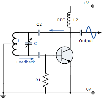
          In the Shunt-fed Hartley Oscillator both the AC and DC components of the Collector current have separate paths around the circuit. Since the DC component is blocked by the capacitor, C2 no DC flows through the inductive coil, L and less power is wasted in the tuned circuit. The Radio Frequency Coil (RFC), L2 is an RF choke which has a high reactance at the frequency of oscillations so that most of the RF current is applied to the LC tuning tank circuit via capacitor, C2 as the DC component passes through L2 to the power supply. A resistor could be used in place of the RFC coil, L2 but the efficiency would be less.

          This one I planned to use, which is very similar to the Slayer exciter circuit is this one:

          Transistor Tutorial, Part 7: Oscillators
          Figure 6 illustrates the Hartley Oscillator, which is a variation of the tuned-collector oscillator that was shown in Fig. 5. This oscillator is recognizable by the tapped coil in its tuned resonant circuit. Oscillation of the Hartley oscillator circuit depends on phase-splitting autotransformer action of the tapped coil in the tuned resonant circuit.

          The tap is located on load inductor L1 about 20% of the way down from its top so that about 1/5 of the turns are above the tap and 4/5 are below. The positive power supply is connected to the tap to obtain the necessary autotransformer action.

          The signal voltage across the top of L1 is 180° out-of-phase with he signal voltage across its lower end, which is connected to the collector of Q1. The signal from the top of the coil is coupled to the base (input) of Q1 through isolating capacitor C2. The oscillator will oscillate at a center frequency determined by its LC product.
          In this design, the bias transistor current (determined by R1) also flows from the PS trough the lower part of L1.

          The Slayer exciter appears to have the same problem:


          Update: Also saw these post:

          Originally posted by stevecmagni1 View Post
          Please try and power a Hartley oscillator with it, they run at power levels of micro amps. Great work in working out practical ways to utilise this strange effect.

          Originally posted by Lidmotor View Post
          In the video I do not have a ferrite rod in that coil with the two LEDs attached. I am using the ferrite core on the small soda straw coil instead as a tuning point. In the video the rod isn't even in that coil. The variable capacitor is doing the tuning instead. I found out that you can configure this circuit in several ways and it will still work. The trick will be to find the best way. Actually it is hard to beat the basic Slayer Exciter circuit. It is so simple and effective. The lure of this particular Hartley oscillator was that it will run on micro amps.

          Does anyone have a schematic of that one? Micro-amps would not be bad
          Last edited by lamare; 07-22-2011, 07:35 AM.

          Comment


          • Ah ha! Phase one of operation pancake is complete: Source suitable materials.

            Bendy MDF, otherwise known as Neatform...


            This will do for winding the coil on It comes in 1220 x 607 x 6mm so I will cut it into narrow strips at 90 degree angles to the existing grooves thus saving the need to spend hours measuring and cutting grooves in strips of pine as per the original idea. The grooves are approx 2mm wide with 4mm between them, but they should be easily widened with a file to fit thicker wire if required.
            http://www.teslascientific.com/

            "Knowledge is cosmic. It does not evolve or unfold in man. Man unfolds to an awareness of it. He gradually discovers it." - Walter Russell

            "Once men died for Truth, but now Truth dies at the hands of men." - Manly P. Hall

            Comment


            • @lamare - Lidmotor uses the Hartley in this vid: ‪Hartley - Slayer Exciter.ASF‬‏ - YouTube
              Slayers' implementation can be seen here: ‪Hartley Oscillator Replication‬‏ - YouTube
              Lidmotors' circuit is here: ‪Cement battery running a Hartley Oscillator Transmitter.ASF‬‏ - YouTube


              @dR - neat find...looks like something you might use in flooring. Inset with a coil in the floor, hmm, bedroom slippers that light up a pathway around the house at night ? lol. The ideas jump forward with that sort of thing eh.

              Comment


              • Originally posted by Slider2732 View Post
                @dR - neat find...looks like something you might use in flooring. Inset with a coil in the floor, hmm, bedroom slippers that light up a pathway around the house at night ? lol. The ideas jump forward with that sort of thing eh.
                lmao! That would be awesome. Dragons' Den here we come! My sister also has USB heated slippers Wireless heated slippers sounds even better
                http://www.teslascientific.com/

                "Knowledge is cosmic. It does not evolve or unfold in man. Man unfolds to an awareness of it. He gradually discovers it." - Walter Russell

                "Once men died for Truth, but now Truth dies at the hands of men." - Manly P. Hall

                Comment


                • Originally posted by lamare View Post
                  So, what is important is that if you want the magnifying effect without transmission of power over a distance, you don't need the capacitances, because you can use the output of the coils directly.

                  If you do want to transmit power trough the earth, water, or some kind of wave guide, you need "something to push against" which would be capacitative sphere, that will always radiate something, but that should be avoided as much as possible.


                  So, sorry for the confusion, it was already late in the evening when I wrote that.
                  Hi lamare, no probs, it is true there are two ways to use a Tesla coil.

                  The end capacitances can still be normal caps like in Don Smiths setup he says that a cap accross one side of the secondary is optional, it would need to be very HV rated and quite small capacitance, this would be a frequency control allowing resonance to be acheived at a much lower frequency and the primary should also have capacitance so that it's sine wave peaks at the same frequency.

                  I think there should be a sine wave on the secondary the unconnected scope probe held or hung near it should see it.

                  With a function generator I was able to easily and accurately determine the correct capacitance to use with my primary coil to make its frequency the same as the secondary, the same applies to the secondary it resonant frequency can be changed by adding capacitance.

                  The thing I found is that if the resonant frequency of the secondary is a lot higher than the primary then far too much capacitance is needed on the primary coil to make its resonant frequency equal to or very nearly the same as the secondary, so in that case the secondary frequency can be reduced by adding capacitance to it in the form of a normal non polarised HV capacitor.

                  Please take a look at the link below on page 10 figure 5 drawing 10 and 11.
                  Nikola Tesla on his work with ... - Google Books

                  Tesla did try that, drawing 10 shows metal balls similar to a spark gap and drawing 11 shows a capacitor connected between the ends of the secondary as well as an antenna.

                  It can work and I will be trying it too when I can. The other side of the capacitor needs to be connected to the other end of the coil or the ground a Toroid or sphere does that. But I agree for making gains from a device joining two coils together is the way to go, for sure.

                  I think the load should go between the ends and the center or two identical loads like i think you mentioned earlier somewhere. Or rectified.


                  P.S However Tesla apparently found that it was much better to reduce the resonant frequency by increasing the secondary inductance, then he could reduce the terminal capacitance to minimal thereby reducing the radiations as much as practical.
                  Last edited by Farmhand; 07-22-2011, 01:28 AM.

                  Comment


                  • Also if you read down three paragraphs he talks about Magnifying the current. He uses the words magnifying or magnification several times in that paragraph. It is the primary current he is talking about which in turn magnify's the current in the Antenna. The magnification of curent is proportional to the ratio of the inductance to the resistance of the circuit.

                    Page 11 paragraph #2
                    Nikola Tesla on his work with ... - Google Books

                    Text
                    https://skydrive.live.com/?cid=32a91...1329&sc=photos

                    This is the patent he refers to in that paragraph.
                    NIKOLA TESLA - Google Patents

                    Last edited by Farmhand; 07-22-2011, 04:37 AM.

                    Comment


                    • The issue of how many turns for the oscillator still not satisfies me. I now have a full wave between the tap for the PS and the tap to the collector of the transistor. But the transistor forms an inverting amplifier, so 180 degree phase shift from base to collector. Since the transistor activates the coil by drawing current and is steered by a very small base current, one would think you need 180 degree phase shift between the base tap and the collector tap, so my first design was right after all.

                      What do you guys think?

                      Comment


                      • Anything is possible lamare, which is the original idea, is that with the coils wound opposite ?

                        It's hard for me to comment when things get too technical. But I think this is definatly a good way to go some way or other, the magic is close I can sense it. I don't wanna miss out. I just did an experiment with a aluminium disc suspened about 8 inch's from the toroid terminal and grounded to form the capacitor as shown in the link above Page 10 figure 5 drawing 11, and it does something very cool. I will make a video later (no time now) to show what I did and how it affects things. I'm a terrible explainer. I'll try to explain what i think in the magnifier thread but i'll link the video here too because I think it is relevent. To all exciters and such, in a way.

                        Cheers
                        P.S. Maybe someone can tell me how it is doing what it is doing.
                        Last edited by Farmhand; 07-22-2011, 06:55 AM.

                        Comment


                        • Originally posted by Slider2732 View Post
                          Thanks!

                          Took a few screenshots of the schematic and the coil. Note that the feedback coil is wound in the opposit direction on top of the activation coil in this case.

                          Also note that with this coil, the feedback coil is 25 turns and the activated coil is 50 turns. So, apparantly you need a half wave between the central tap and the emitter of the transistor and a quarter wave between the centrap tap and the feedback to the base. So, that would mean for my coil: 12 turns for the feedback and 24 for the one to be activated by the transistor. If that is correct, then it appears you can treat the steering of the transistor to be by voltage and very low current, so you need to tap it one quarter wave further because of the 90 degree difference between current and voltage.

                          Looks like the best thing to do is to add an (or 2) extra tap(s) to the full-wave section of my coil, so I can easily change and just see what works best in practice. If the theory is confusing, then practice should be leading....


                          Update: Found another version of this same schematic:

                          Identifying Wildlife Tags


                          It says that this one does not produce continous oscillation:
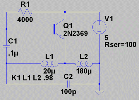
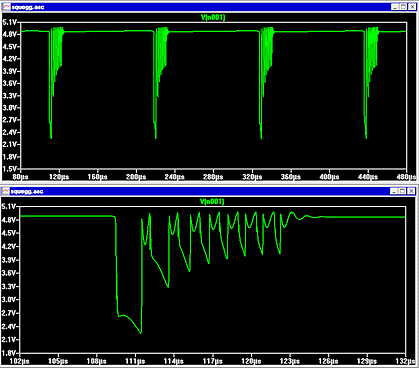
                          The combined inductance of L1-L2 is resonated by C2 to set the oscillator's RF output frequency. The RF would be continuous if feedback conditions were stable. But in this circuit, C1 charges in just a few RF cycles and saturates the transistor, then discharges more slowly. The result is short periods of oscillation, as shown in the waveforms of Figure 2.


                          The 100pF C2 determines the oscillation frequency, together with L1/L2. I saw in Lidmotor's video that he could adjust the oscillation frequency, which he appeared to be doing by adjusting the potmeter (variable resistor). While it suggests that C1 is being charged by RF, it is being charged by the DC path from the PS trough R1 at the top and trough L1 and L2 to ground...

                          Since I can't spot any significance difference between the two schematics, and Lidmotor's frequency adjustment stuff, it looks like we have to add some modifications to make it oscillate continously.


                          Update 2: Here's another one:

                          HARTLEY OSCILLATOR - Circuit Diagram - Forum - SeekIC.com

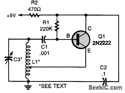
                          The oscillator's operating frequency is determined by the values of L1 and C3. The feedback level is determined by the location of the tap on L1, which normally will be about one-fifth to one-fourth of the total turns. As an example, the Hartley oscillator will operate in the 5-MHz range with the following LC values: L1 is 20 turns of 18 enameled copper wire close wound on a 1-inch plastic form with a tap up five turns from the bottom. Capacitor C3 can be any small variable capacitor with a maximum capacitance value of 100 pF. With the proper LC values, the Hartley oscillator can operate from audio to UHF.
                          Note that the resistor between base and collector of the transistor is significantly bigger than one oscillating in burst mode. So, indeed the cap is charged trough the resistor and apparantly if the resistor is sufficiently big, you get continous oscillation.


                          Update 3:
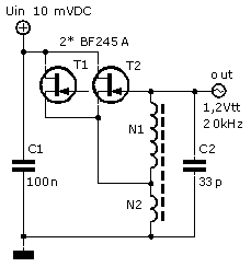
                          Here I found one that is capable of running on 10 mV :

                          Extreme Laagspanning Oscillator :: Elektronica Meettechniek


                          A quick translation of the accompaning text:

                          For the design of an extreme low voltage-oscillator, the Hartley version has been chosen. With this type of oscillator there is a direct DC-coupling between gate and source trough N1 of the transformer. Hereby the DC bias Ugs = 0V of the J-FET is established.

                          In order to get the oscillator functioning at 10 mV power supply it turned out that the amplification of one J-FET was insufficient. By switching two in parallel enough amplification could be created.

                          The oscillation frequency is about 20 kHZ and the output voltage is about 1.2V. At 10 mV it draws about 70 uA.

                          The turns-ratio of the transformer makes sure there is enough AC voltage at the gate to get the oscillator into operation.
                          The energy this oscillator delivers is very small. The load of a measuring instrument can already be too much. When testing we used an oscilloscope with a 1:10 probe with a resistance of 10 M and a capacity of 12 pF.

                          The transformer has been wound on a Amidon EA-77-199 core. N1 is 900 turns 0.5 mm and N2 is 4 turns of copper strip with a thickness of 50 um.

                          The article also says that a J-FET is very suitable for circuits working at extermely low voltages, because bipolar transistors suffer from PN junction-voltages of 500-600 mV at small currents. It also says the BF245A is the most suitable of the 4 types shown, because it has the lowest DC current and the highest gain.


                          Update 4:
                          Here's someone that manages to go as low as 5.5 mV supply voltage, and 0.41 mA :
                          Oscillator with super low supply voltage


                          And he manages to run it from....


                          ...a candle-powered thermocouple!!

                          Thermocouple - Wikipedia, the free encyclopedia


                          Oscillator powered by a thermocouple.

                          The oscillator described above (version 6) is now connected to a thermocouple.
                          The thermocouple is one as used in gas heaters.

                          The thermocouple used gives about 13 mV when heated by my soldering iron (370 °C).
                          In or just above a candle flame, the output is about 20 mV
                          In a gas flame, the output is about 40 mV, and the thermocouple is then red hot.

                          The pictures below show the test set-up of the oscillator, and the thermocouple above the candle flame.

                          The oscillator is running very well on this "power supply"


                          I feel the arrival of vids showing candle-powered Joulethiefs lighting fluorescents coming.


                          This fellow also says a JFET is the best choice for low voltage:
                          A junction FET is used because these FET's already conduct at zero gate voltage (Vgs= 0V).
                          Other active elements like transistors or most MOSFET's need a certain voltage at the input before they start conducting.
                          And we don't have such a voltage when the oscillator is powered from a super low supply voltage.
                          Attached Files
                          Last edited by lamare; 07-22-2011, 01:25 PM.

                          Comment


                          • Originally posted by Farmhand View Post
                            Also if you read down three paragraphs he talks about Magnifying the current. He uses the words magnifying or magnification several times in that paragraph. It is the primary current he is talking about which in turn magnify's the current in the Antenna. The magnification of curent is proportional to the ratio of the inductance to the resistance of the circuit.

                            Page 11 paragraph #2
                            Nikola Tesla on his work with ... - Google Books

                            Text
                            https://skydrive.live.com/?cid=32a91...1329&sc=photos

                            This is the patent he refers to in that paragraph.
                            NIKOLA TESLA - Google Patents

                            Farmhand, the magnification of current in the primary he is talking about refers to the discharge of a capacitor into an inductor. When you charge a cap and dump it into a low inductance it gets converted to amperage. The formula is V(C/L)^.5 = current at 1/4 cycle.

                            For instance say we charge a .005 uf cap to 6500 volts and discharge it into an inductance of 3uh. You would have a discharge equivalent to 265 amps flowing through the inductor. ( 6500*(.005/3)^.5 = 265.36 ). Typically the primary coil is very large and extremely low resistance.

                            Tesla also reports that placing a foil near the primary coil will explode the foil in a flash which would indicate a huge inductive heating effect of a resonant circuit caused from the high amperage flowing in the coil.

                            The hammer that rings the bell...

                            Comment


                            • Originally posted by dragon View Post
                              Farmhand, the magnification of current in the primary he is talking about refers to the discharge of a capacitor into an inductor. When you charge a cap and dump it into a low inductance it gets converted to amperage. The formula is V(C/L)^.5 = current at 1/4 cycle.

                              For instance say we charge a .005 uf cap to 6500 volts and discharge it into an inductance of 3uh. You would have a discharge equivalent to 265 amps flowing through the inductor. ( 6500*(.005/3)^.5 = 265.36 ). Typically the primary coil is very large and extremely low resistance.

                              Tesla also reports that placing a foil near the primary coil will explode the foil in a flash which would indicate a huge inductive heating effect of a resonant circuit caused from the high amperage flowing in the coil.

                              The hammer that rings the bell...
                              Yes that's right, lots of current for a big thump. I hopeless with figure's but i'll try to work it out, thanks for the formula, it doesn't look too difficult. My fluro's turn black on the ends in a short time, a few hours use and they get hot on the end too. I just used 25 volts for the input voltage and could get 800 Ma through the primary thats 20 watts, the voltage at the receiver was 63 volts in a 200 uf cap while powering 4x5mm LED's through a 1k resistor the resistor started smoking and turned black. So I backed off. This was while experimenting with the aluminium plate elevated near the toroid but grounded like one side of a cap. If it is tuned properly I cannot make any sparks with it because that de-tunes it.

                              I changed out the diode's at the receiver to FR307's the 1N4007's were getting hot, as lamare said they cannot handle anywhere near the frequency we use. And I don't think 1n4148's would have lasted long.

                              Really a lot of fun. I can adjust now so the voltage at the receiver is variable and the input go's to very little less than 100Ma at 24 volts though and still have 20 volts at the receiver cap with the LED's lit. And when adjusted like that with the cap plate the radiations from the wire are reduced dramatically aswell.

                              I'm goung to try 160 volts from some caps filled by an inverter tomorrow. That should get some watts through that primary.

                              Cheers

                              Comment


                              • Hi gang,
                                Apologies for my absence. Been quite busy with work. I have 16 employees now so it keeps me on my toes. I've still been playing with thenexciter. I don't know whether to call it slayer or stiffer or what ever lol. I posted thisnvid a week or so ago which shows the setup ‪Stiffler exciter‬‏ - YouTube

                                In that vid I'm using a 1818 transistor. I don't use any resistor or diodes and start the oscillations using an av plug. What has me perplexed ATM is that I have been playing with the circuit on page 7-9 of Patrick kellys book, which is a "cosmic energy receiver" (my term) to test if my circuit could actually receive energy I decided to use my exciter as a transmitter. I'm using a piece of aluminum as the antenna. When it is about 1' from my exciter it charges the caps up. However when I stop the oscillations on the exciter (switch it off) the voltage on the caps jumps and climbs steadily for 10 secs doubling the voltage in the caps. WTF is going on there? Apologies if I have not provided enough info with my limited knowledge.
                                Stew Art Media

                                Comment

                                Working...
                                X