Announcement

Collapse
No announcement yet.

Joulethief SEC exciter and variants

Collapse
X
 
  • Filter
  • Time
  • Show
Clear All
new posts

  • lol@Wallace

    Well hey Grommit, it runs !
    I connected the winds end/start/end/start etc on each side and then connected up as per the diagram a couple of pages back.
    MJE13009L transistor, 1K pot and that's it for now. Will try caps across the pot, the diode to the Base Lasersaber mod and whatever, but it works.
    The main thing with this one, is that it uses the wire that comes straight off the CRT neck. Only the 2W LOA LED bulb and the pot haven't come from the monitor.
    200mA draw is a bit large and this toroid sings away merrily, but have enjoyed that build.

    Here's a short video of it (plus a couple of salts type batteries).
    Sorry about the dirtied hands, had just taken the rest of the monitor parts and other gubbins back outside again.

    1.5V mains lightbulb + Sea cell seashell battery - YouTube

    Comment


    • Originally posted by woopy View Post
      ....
      So in summary , my accidently broken in 2 parts standard toroid is far the best. Especially in the ability to melt and create long plasma arc.

      I also include the scope trace of the Standard toroid at about 12 volts input and with the max plasma arcing.
      chanel 1 is the input positiv current (from the power supply) accros 1 ohm resistor. And chanel 2 is the signal probe on one of the elctrode lead wihtout grounding.
      So Gyula there is effectively a strong assymetry in the AC .

      i will of course study in more deepness all your proposal, but need some time to digest all the info.
      ....
      l
      Hi Laurent,

      It is unfortunate your LC meter got wrong, it would help in comparing the 3 different toroids you show, what the individual coils would measure. Permeability of the cores, together with the airgap sizes, which surely counts and a coil with higher L value in the transistor collector (generally) results in less current draw, of course the ON time of the transistor influences this.
      Would like to ask if your broken toroid windings are distributed in the same way as your other two TV yokes? (On one half part only the secondaries, on the other half part the collector-base coils) Because in your first video on Sergdo circuit ( Amazing light with low power toroid transformer 1.wmv - YouTube ) around time 1:47-1:52 it seems to me you wound one primary and one secondary on one broken half and the other primary and the other secondary on the other half?
      I think perhaps the best remedy against the asymmetry in the output waveform would be to split the collector coil into 2 x 10 turns and place 10 turns on one half and the other 10 turns onto the other half of the cores then connecting them in series aiding because the collector coil carries the highest DC peak current, the other 20 turns primary to the base carries 1/Beta times less current (Beta is the current amplification factor of the transistor, roughly Ic/Ib). Another factor for causing asymmetry could be the 'almost' uniform size of the broken toroid half parts: inductance for one secondary coil on one half part can be different than the inductance on the other half part, considering equal number of turns (reason is air gap BUT we do not have to take airgap as an enemy here because it helps against saturation). If the secondary inductances differ from each other, perhaps winding a few turns more on one half side could help reducing asymmetry too.

      Seeing your latest scope shot on the asymmetry in output waveform and comparing it to the much smaller asymmetry in your above February 25 video, what is the difference: the supply voltage i.e. now you have higher input power, this may mean higher possible saturation in the cores and the operation point of the transistor can also be different. IF you watch the loaded output waveform and turn the base potmeter towards higher value: does the asymmetry improve or stay more or less the same? If it stays, try to change power supply (say lower it) and again turn the pot. And in case you find a small asymmetry "sweet operational point" and the output amplitude is small, then you would have to increase the number of turns on the two secondaries...

      Good experimenting!

      Greetings,
      Gyula
      Last edited by gyula; 03-03-2012, 11:07 AM.

      Comment


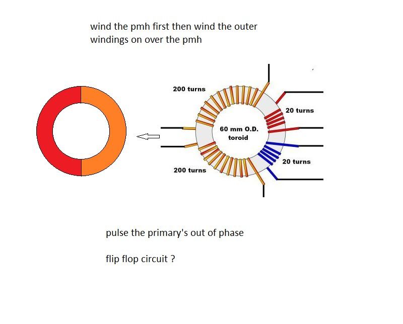
      • Wind Ed's pmh under the windings.


        Power the primary's with a flip flop circuit, creating an out of phase situation that will be reflected into the secondary's .

        And go ou.
        Half of the Answer is knowing the right Question

        Comment


        • Half of the Answer is knowing the right Question

          Comment


          • Hi all

            Ok today i decided to violate one of my own law , that is never dismantel a prototype machine , even if it does not work yet.
            And this , because it can perhaps be one day ,with some more knowledge, i can get this stuff out of the drawer and with some modif , make it work finally.

            But some time you have no choice and when you get a almost perfectly 1/2 x 60 mm diameter broken toroid you ask if it does not worth the work.

            So i did it and dismanteled my best working toroid to try an other way and see if there is some difference.

            So i wound 500 turns x 2 on one half toroid With 7 stranded litz wire (from Romero experiment ) and got 6.7 ohms DC resistance per winding.
            And 50 turns x 2 on the other half of toroid with 0.4 mm copper wire.
            So i got 1 to 10 ratio between the 2 toroid halves

            So i got very good succes with LED lighting at around 9 volts and 0.2 amp, See scope pix
            But almost no power for the steel melting . and a very noisy (hissing ) small plasma arc.

            Than i decreased the Collector and base number of turns to 40 turns and than to 30 turns .

            The melting was there but poor. Than i tried with the diodes bank (as per Sergdo ) and i got very powerfull continous melting , as per my previous experiment, But i coulkd not be able to get any measuremenr because, after some minutes at 12 volt and arround 500 ma (arroud 6 watt of powerfull melting )the already known winding arcing appears somewhere in the winding and .....finished for today :

            Ok summary

            the output of the secondaries is a verystrong assymetrical AC and seems not to depend of the winding or the separeted core vertical or horizontal.

            Depending of the ratio between the primaries (joulethief part ) and the secondary, you can get a very efficient LED lighting but few steel melting.

            If the above ratio is more than 1/16 , and if you use the diode as per Sergdo, you will get strong steel melting at low input power, but with very high risk of destructiv arcing in the enameled copper winding.

            So for me now is to find A VERY WELL INSULATED ENAMELLED COPPER WIRE WHICH CAN HANDLE THE REALLY HIGH VOLTAGE PULSES in the secondaries.

            And can somebody explain me why ( in the sergdo circuit ) the diodes increase so much the steel melting ???

            hope this helps

            good luck at all

            Laurent
            Attached Files
            Last edited by woopy; 03-03-2012, 11:28 PM.

            Comment


            • Theorem

              One fundamental electric theorem is that the amount of current entering a node is equal to the amount of current leaving the node. In other words, electricity doesn't disappear or reappear out of nowhere*. I've wound a secondary winding onto a JT core and I have also found that if I connect two LEDs in anti-parallel (back-to-back) and connect them across this winding, one LED is brighter than the other, indicating that there is an asymmetry in the current flowing in the winding.

              * Obviously this isn't applicable to an antenna, right...

              Originally posted by woopy View Post
              Hi Xee2

              My question is exactly what you point out

              is it a difference of the nature of energy on the output secondaries.

              is it simply more or less energy on one side and less or more of the same energy on the other.

              or
              Are we dealing on the fact that on one side we have a "cold " or better sayd perhaps soft radiant ....energy .and on the other side a "hot " and so brutal
              energy that it can MELT steel .

              Is this Sergdo's winding organising a transfer of this cold overall radiant energy to a hot powerfull and usefull energy by using the plasma arc ?

              youpp thinking out of the box here

              am prepared for bombing attack do not worry

              good luck at all

              laurent

              Comment


              • Hi Laurent,

                Thanks for your excellent efforts and dedication.

                I think if you could rewind the 2 x 400-500 turns secondaries by using insulating tape between each layer then arcing could be minimized. First check with a MegOhm meter the surface of the toroid (I know it has a bluish covering, supposed to be an insulator but just check with the measuring tips 5-10mm apart how big the resistance is, must be in the MOhm range or open circuit) and then wind the first layer of the coil, then use one layer insulator tape, then second layer of the coil and so on.
                I think this would be worth testing whether arcing remains, it should not because the 500 turns/350V does not give much voltage difference within the neighboring turns BUT it can give big difference between layers, helping arc.

                On ebay, there are copper wires with 600V insulation ratings but I found only rather thich ones. Perhaps among the "magnet wires" category search the High Temp ones I guess their insulation is improved voltage-wise too.
                Here is another "heavy formvar" wire but I do not know its insulating properties:
                34 AWG HEAVY FORMVAR MAGNET WIRE 1000 FEET | eBay

                Re on your question with the diode: I think if the electrons can go one way only, due to the diode polarity (versus the AC case even if it is asymmetrical) then heat can accumulate better (as Caroll explained for the DC welding).
                However, what I suddenly cannot get: why Sergdo did not use a full wave bridge? especially with a HV puffer capacitor (some hundred nF)?
                As he uses the two diodes, is not one of the diodes shorted out? Willl check his video again, perhaps this is clear for you?

                Thanks, Gyula

                Comment


                • Originally posted by gyula View Post
                  ...

                  As he uses the two diodes, is not one of the diodes shorted out? Willl check his video again, perhaps this is clear for you?

                  Hi Laurent,

                  I checked both Sergdo and your video on the HV diodes connection (you show it here: Amazing melting with low power transformer 1.wmv - YouTube ) and the strange thing is Sergdo placed the 'load' i.e. the melting wires across one of the diodes (across his left hand side HV diode in his video) and this is very unusual. If DC voltage is preferred for melting than a full wave diode bridge would seem desirable (Sergdo's rectification seems to be half wave only...) and as I wrote some hundred nF 2-3kV rated puffer capacitor would be also good across the bridge output. You could test this with even the 1N4007 diodes by putting at least two in series in each diode place inside the FWB, I know these diodes are not so good in the kHz range but for a quick test they would serve. A better, faster diode is the also 1000V / 1A rated UF4007 (UF= Ultra Fast).

                  rgds, Gyula
                  Last edited by gyula; 03-04-2012, 10:53 AM.

                  Comment


                  • I don't get it .. nobody see that it's exactly what Don Smith tabletop device had on output ! Woopy, just measure average voltage after diodes, and try to ground to Earth ground (good one) via varistor and all whan is needed is a huge capacitance capacitor rated to that voltage. The of course power inverter like Don Smith used. I think 100-200W at least could be possible from that small toroid

                    Comment


                    • Oscillating the primary's
                      TROS alt-lighting V - "transformer" - YouTube
                      do this with woopy's coil
                      Half of the Answer is knowing the right Question

                      Comment


                      • Originally posted by boguslaw View Post
                        I don't get it .. nobody see that it's exactly what Don Smith tabletop device had on output ! Woopy, just measure average voltage after diodes, and try to ground to Earth ground (good one) via varistor and all whan is needed is a huge capacitance capacitor rated to that voltage. The of course power inverter like Don Smith used. I think 100-200W at least could be possible from that small toroid
                        Sandwich two neo's between the toroid halves

                        Need another bobbin then I'll start winding the secondary's
                        Half of the Answer is knowing the right Question

                        Comment


                        • Originally posted by woopy View Post

                          And can somebody explain me why ( in the sergdo circuit ) the diodes increase so much the steel melting ???
                          That is a very good question. The diodes shorted by the melting wire do not seem to add anything to the circuit since theoretically there would never be any current flowing through them. That is what got me interested in this circuit. If you have not already done so, see if there is a difference between when using just the string of diodes in series with the melting wire and when using both strings of diodes. This is a real puzzle.

                          As for the arcing, this can be prevented if you keep the wires at the input side of the inductor away from the wires at the output side of the inductor. The voltage between adjacent wires is low, the high voltage is between wires at the ends of the inductor. I wind layered coils in sections, with a bunch of layers in each section, so that the voltage is divided by the multiple sections. The sections do not have to be physically separated, they can be wound next to each other. Use at least three sections so that the input side section wires are separated from the output side section wires by the middle section.

                          Comment


                          • hi all

                            yes this morning i rewound the 2 x 500 turns 0.3 mm enameled copper wire, with an insulation with masking tape between each layers ( long and boring job )

                            but well worth (thank's Gyula). the primaries are always 20 turns 0.4 mm.

                            And i got at once the very efficient steelmelting. I melt the 0.3 mm diameter steel (ferromagnetic ) with arround 5 watt easily.

                            See pix of the toroid and circuitery and a scope shot during the melting.(channel 1 input current across 1 ohm resistor, channel 2 = the sensing probe is not directly connected to the melting leads because the voltage is far above my scope possibility )

                            I confirm that the diodes is needed in this config to get a nice continouus melting with nice sparkling of metal. And without the diodes i only get a dizzling blue plasma arc (seemly cold on the both ends )

                            Can not elaborate more today.

                            hi Boguslaw

                            Can you draw your meaning please.

                            hi Dave

                            Will study the question thank's

                            good luck at all

                            Laurent
                            So far no arcing up to 10 volt input
                            Attached Files

                            Comment


                            • Originally posted by boguslaw View Post
                              I don't get it .. nobody see that it's exactly what Don Smith tabletop device had on output ! Woopy, just measure average voltage after diodes, and try to ground to Earth ground (good one) via varistor and all whan is needed is a huge capacitance capacitor rated to that voltage. The of course power inverter like Don Smith used. I think 100-200W at least could be possible from that small toroid
                              Don Smith circuits do not work. Many people have replicated them and none of them produced more energy out than was put in. Charging a capacitor does not increase energy, it just stores up energy put in over a long time and releases it in a short time. The energy out is not greater than the energy in, it just has a higher current because it is being transferred in a shorter time.

                              Comment


                              • What would happen if you have two systems like these back to back, in order to reduce the high voltage to a low voltage again. With a bridge rectifier and cap energy output can be easily measured across a load.

                                Comment

                                Working...
                                X