Announcement

Collapse
No announcement yet.

Joulethief SEC exciter and variants

Collapse
X
 
  • Filter
  • Time
  • Show
Clear All
new posts

  • Hi folks, very cool stuff, lighting incandescent bulbs.
    I remember awhile back running 24 volts on my exciter and it caused loud audible noise from a clock radio 30 feet away, the radio was not turned on.
    Hi slider, thanks for vids and info., when you put bulbs in parallel, does each added bulb cause the other to get dimmer, thanks.
    peace love light
    tyson

    Comment


    • Originally posted by Slider2732 View Post

      Update
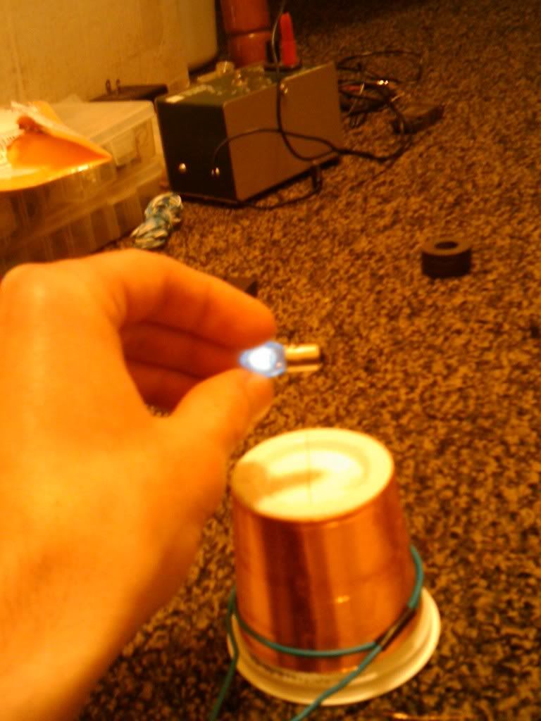
      Ha, how easy was that, 2 minute thing and this 6.3V bulb lit up on the main tower !
      Next, to see what happens further afield.
      Very cool Woopy and Seth


      Just found out, that if you put a tiny 12V 'ear of wheat' also on the loop (the bulbs for Bedini wheels) then the main 6.3V bulb doesn't seem to lose any brightness.
      2x 6.3V bulbs light well, more can be added to the same loop as well, in parallel !
      In parallel is how its drawn in the Tesla patent.

      I can't believe I've been playing with it for this long, and never tried 'stepping down' the voltage and getting some real ampage. I cant wait to finish work and have another go.

      Er - never tried isnt true. I HAVE tried....and failed every time. Until I saw the Woopy video. Thanks again!
      Attached Files
      Last edited by seth; 04-13-2012, 08:12 AM. Reason: Clarification

      Comment


      • The thing is, we over complicated it, well at least I know I did.
        It was like a lightbulb going on in the mind, simply close the loop of wire with the bulb !
        A classic case of RTDM lol, thanks Mr. Tesla.

        Yeah Tyson, you only get so much, same as the limit for drawing from the field 'conventionally'. But, if you pair up the right bulbs, then some strange enough effects are seen.
        What I have is a small bag of bulbs, collected from household stuff and one of those $2.49 random assortments from Electronic Goldmine ( Small Incandescent Lamps-The Electronic Goldmine ). The 'ear of wheat' are about that price each from Radio Shack, so I was fortunate to find 5 of them in the pack, when needing 3 for a project.
        Mixing and matching of different draw bulbs has been interesting. You may expect a 12V bulb to draw more than a 6.3V bulb, however, if you go by internal gas volume then you find more of a correlation for tower output. Kinda weird.
        For example, the 6.3V bulb is about 4x larger physically than the 12V ear of wheat. Putting 2x 6.3V bulbs in parallel drops the output, but adding a 12V ear of wheat to a 6.3V doesn't seem to make a difference to the light from the 6.3V. Due, to the 6.3V having a larger internal volume - as a theory. Whether that is correct I don't know, just looks like it from my tests
        Certainly, the smaller the bulb of no matter what DC rating that I have here, the less impacting draw is seen.
        So, what i'm saying is, the rated normal running voltage of a bulb from a conventional DC supply, needn't be the case factor in bulb brightness.

        Many flashlight type bulbs won't display the corona plasma internally, no matter what. But, will fire up to full brightness on the single turn of thick wire.

        Also bear in mind, that we're not seeing a standard transformer action here. As seen in my pic on the previous page, while you get a good step down action for the DC bulbs, you also have the AC emissions STILL present.
        Lighting DC bulbs did not impact the small flouro lit wirelessly (as seen) but also allowed a remote 6ft away LED to stay illuminated.
        Last edited by Slider2732; 04-13-2012, 04:16 PM.

        Comment


        • Hi folks, Hi seth, thanks for tesla patent picture.
          Hi slider, indeed, I don't think tesla type setups as this use standard type transformer action, which is why I was wondering what you are seeing.
          That is encouraging, that your fluorescent bulb is not affected by the one turn secondary and bulb or bulbs.
          food for thought this is for sure, thanks for your effort slider and all.
          peace love light
          tyson

          Comment


          • High frequency amp meter

            I thought some of you could find a good use for this.

            Its a "how to" on building a HF amp meter using an analog DC amp meter.

            Build yourself an RF Ammeter

            Comment


            • Here is a very simple exciter circuit.It's just a variable capacitor ,2n2222 transistor, 1M resistor, bobincoil and a couple Dr Stiffler towers.

              You don't have to use the Stiffler towers it will work with about any smaller size coils.
              But you do need the capacitor for this to work.

              Simple Exciter - YouTube

              Comment


              • @ Slayer:
                Thank you for sharing your circuit. It looks like it's running very well on 6v, 10mA, or less.
                Since the Doc has not been posting lately, I'm very glad to see that you as well as a couple of other people are still at it.
                Your work is much appreciated, and not overlooked.

                My hope is to use a circuit such as yours, that will run off of my homemade cells, which now can produce the output that you are now using from the 6 volt source. And hopefully someday I'll able to add more cells on, to increase the led output brightness to a more useable level, that can light a whole room, at least to low light but useable levels.

                Pictured below is a different type of Jt circuit, and a cell that I rebuilt yesterday. The circuits uses no resistor, a KN2222A transistor, and a small ferrite core, RS 10mm led. It is running off a single homemade cell, which can maintain an output of 0.65 volts, and about 30mAs, and it can light 6 or more leds, to about 1/2 brightness.
                I would like to replicate your circuits though, as it looks like wireless transfer is more efficient than what my circuit(s) are producing.

                Thanks again, for all your great videos, and outstanding work on these amazingly efficient circuits.
                NickZ
                Last edited by NickZ; 04-29-2012, 05:58 AM.

                Comment


                • Originally posted by NickZ View Post
                  @ Slayer:
                  Thank you for sharing your circuit. It looks like it's running very well on 6v, 10mA, or less.
                  Since the Doc has not been posting lately, I'm very glad to see that you as well as a couple of other people are still at it.
                  Your work is much appreciated, and not overlooked.

                  My hope is to use a circuit such as yours, that will run off of my homemade cells, which now can produce the output that you are now using from the 6 volt source. And hopefully someday I'll able to add more cells on, to increase the led output brightness to a more useable level, that can light a whole room, at least to low light but useable levels.

                  Pictured below is a different type of Jt circuit, and a cell that I rebuilt yesterday. The circuits uses no resistor, a KN2222A transistor, and a small ferrite core, RS 10mm led. It is running off a single homemade cell, which can maintain an output of 0.65 volts, and about 30mAs, and it can light 6 or more leds, to about 1/2 brightness.
                  I would like to replicate your circuits though, as it looks like wireless transfer is more efficient than what my circuit(s) are producing.

                  Thanks again, for all your great videos, and outstanding work on these amazingly efficient circuits.
                  NickZ

                  Thank you NickZ

                  This circuit still needs a little work the performance isn't bad but it isn't great eather.

                  One thing I meant to show is that the second tower will light the leds brighter than the main tower.And this will also run with no primary coil at all.Just a wire from the collector to the positive and it will still work but not as near as good.

                  The setup your showing with the cell looks very impressive.
                  Last edited by slayer007; 04-18-2012, 02:45 PM.

                  Comment


                  • Hey guys I've been playing with slayer circuits for a while and I must say
                    THEY ARE AWSUM and I'd like to thank Gbluer or slayer for sharing it here is a pic of
                    my setup creating a plasma ball inside a incandescent flashlight bulb

                    Comment


                    • Say Slayer, I tried out the bobbin idea circuit last night, but wasn't sure of connections. I presumed the bobbin came off the collector and Positive supply, the variable capacitor over the power connections and the secondary tower feeds in to the base...but didn't get anywhere at 3.7V. Will have a better look at it hopefully this evening.
                      Your output was great from that circuit and i'd like to increase range, by tuning more, rather than all from the tower being in a very localised field.

                      Leviathan, you have completely the wrong name for the size of your tower but completely the right name for its output !
                      Yogurt carton ?
                      If we look at Tesla's towers, where do we ever see Greek pillars ? lol. I mean, your design there is something to replicate for the smaller towers. What's the running voltage and current ? Is it about 40 gauge for the secondary ?

                      Comment


                      • @Leviathan
                        That is a Great looking exciter.


                        @Slider
                        It sounds like you have everthing right.You may have to use a higher voltage source.I think your voltage is just to low to see anything.This setup will run very good on 6v to 12v or more.

                        Comment


                        • Thanks slayer, and yup slider it was strawberry favored
                          this system is running on 12v but the reason you cant see a streamer is
                          because im touching the light bulb to the end of the wire, when nothing is
                          touching the wire it makes a strange sort of discharge, looks like plasma but
                          does not act like plasma when ever it forms in the air it creates a perfect
                          "tube" for lack of a better word also depending on the length of the wire sometimes it will create a V two tubes one usually longer than the other it is also affected by magnetic fields. I've played with plasma discharges before and
                          never have I seen a perfectly round and straight discharge let alone a V
                          formation, these circuits are very neat and it appears that there is more than
                          there than meets the eye, needs further research

                          Comment


                          • I've got pineapple, do you think it will still work ? lol, hmm fruity tower building.

                            Yes, the discharges are different because (insert disclaimer here) they run fundamentally differently to spark gap towers. Cleaner in some ways, because (insert second disclaimer here) a spark gap has an element of random fire between the two points and a transistor will always switch at a much more constant running speed. Spark gap towers also run at a few thousand kHz, rather than up to a few MHz of transistor based designs.

                            You'll see the tube type discharges even when up to around 2" in length, they remain that purple and stay tube like. You'll get sparks of yellow at the extremities sometimes, but nearly always the purple.
                            The breakout from a less than sharpened end point will see multiple plasma discharges, the forked V being a sign of that.
                            If you over power the heck out of thin gauge wire, you may see multiple breaks, including before the end, where the wire insulation has been broken through.
                            There's a lot to be experimented with, with different end gauge wire...sometimes a thicker wire will produce a better plasma output, if flux soldered to the end of fine wire. My plasma speakers have featured that, audio was cleaner and louder from the plasma. If merely tack soldered, the bugbear of a breakout at the join occurs.

                            Comment


                            • Hi all

                              perhaps it can be also of interst here

                              amazing sparking between car coil and kacher 1.wmv - YouTube

                              good luck at all

                              Laurent

                              Comment


                              • lol Slider I duno about using a pineapple carton you might not get the right
                                flavor of EM field But I definitely agree with you about the different gauges
                                of wire effecting the output, I was winding a coil the other day and ran out
                                of wire half way through so I substituted for a slightly smaller gauge, that coil
                                had much longer streamers than the other coil that was exactly the same
                                shape but with a larger gauge.

                                Very Impressive setup Woopy, I am at a loss of words it looks like you have a capacitor
                                sitting inside of a coil thats oscillating and the capacitor is receiving energy from the
                                coil, very interesting I don't see how that could operate with conventional electronics,
                                but then again many things do
                                Last edited by Leviathan; 04-20-2012, 05:52 AM.

                                Comment

                                Working...
                                X