Announcement

Collapse
No announcement yet.

Joulethief SEC exciter and variants

Collapse
X
 
  • Filter
  • Time
  • Show
Clear All
new posts

  • xee2
    replied
    Originally posted by woopy View Post
    Here a better pix of the setup.
    Laurent
    Thanks. Is the following what you have? The diodes do not make any sense to me.


    Or is it like this?

    Last edited by xee2; 02-26-2012, 09:33 PM.

    Leave a comment:


  • woopy
    replied
    Hi Xee 2

    Here a better pix of the setup.

    What is very strange is that the circuit is shorted by the diodes ???

    Sergdo uses 2 big diode, that's why i decided to serie 6 time 1n5408 per each side.

    Just for info, this afternoon i wanted to increase the input voltage to improve the melting, and after some minutes. the secondary winding begin to arc inside, and i could only use very low voltage, So i decided to rewind the 2 secondaries with 0.4 mm copper wire. Now i have a DC resistor of 4 ohms on each secondary, and i can already melt at less than 9 volt.

    Hope this help

    good luck at all

    Laurent
    Attached Files

    Leave a comment:


  • xee2
    replied
    Originally posted by woopy View Post
    and for the interested

    good luck at all

    Laurent

    Amazing melting with low power transformer 1.wmv - YouTube
    That is very impressive. The video has wires hanging in fromt of the schematic. Can you please add a schematic to your post.

    Leave a comment:


  • woopy
    replied
    melting steel with a 10 watt torroid transformer

    and for the interested

    good luck at all

    Laurent

    Amazing melting with low power transformer 1.wmv - YouTube

    Leave a comment:


  • woopy
    replied
    Hi all

    surely also of interest here, the "sergdo " thread at OU

    and my replication attempt

    good luck at all

    Laurent

    Amazing light with low power toroid transformer 1.wmv - YouTube

    Leave a comment:


  • mikrovolt
    replied
    I was looking at linear/non linear aspect of spectral content.
    I found this video helpful, for some here just a refresher.
    @ 31:05 he turns down the power supply and the non-linearity starts to kick in.
    I thought it might pertain to SEC when the threshold of semiconductor junction
    approach the cut off point it is simular to when SEC set at the critical edge of threshold.
    Tutorial on Linear and Non-linear Circuits - YouTube

    Leave a comment:


  • marxist
    replied
    woopy-way of lighting LED lamps

    Hi woopy,

    1)
    thank you for making you latest interesting and well explained videos about your exciter/kacher.
    flyback study with a Kacher 1 .wmv - YouTube
    and
    flyback study with kacher 2.wmv - YouTube

    To me the interaction between the LED-bulbs and the coils around them is very intriguing.

    2)
    It would be interesting to see, whether this also works, when only a simple LED is used instead of the Philips lamps.

    If the effect does not appear with a simple LED, then somebody has to find out, what is in these bulbs, apart from the LED(s). Is it a capacitor?

    What is in these lamps that creates the field which interacts so nicely with the coils you wound around the lamps?

    3)
    It would be also interesting to find out (i.e. to scope) the Voltage between the "LED-coils" and the ground (or the antenna). Is it AC or DC?
    And if it is DC, which side is the positive potential? The ground/antenna or the coil?

    4)
    I also wonder if it would be possible, to put a load into the ground-line (antenna-line). In other words to put a load between the "LED-coils" and the ground/antenna?
    Last edited by marxist; 02-05-2012, 10:06 AM.

    Leave a comment:


  • jonnydavro
    replied
    Air feedback exciter 2 - Low power plasma.

    Hi .Here is an exciter circuit,based on my earlier air feedback exciter which seems to produce plasma efficiently.
    I have had plasma bursts and a cfl lighting under 1ma draw.
    It uses a 240vac/18vac step down transformer for the power supply,rectified with a small value smoothing cap as I think this circuit relies on a spikey supply to work.
    I am not to sure exactly what is going on with this one so any thoughts,advice is welcome.Jonny.
    Air feedback exciter 2 - low power plasma - YouTube

    Leave a comment:


  • xee2
    replied
    simple one wire circuit

    Here is a simple one wire circuit. More info at >>> xee2vids's Channel - YouTube

    Leave a comment:


  • kcarring
    replied
    Originally posted by xee2 View Post
    Looks like a Tesla coil. How well have you been able to get it to work? The disadvantage is that the frequency is set by generator. In the Slayer design the frequency automatically adjusts to the self resonant frequency of the coil which is the frequency for best performance.
    @xee2
    I think you pretty much summed it up / said it. Seems that when you stray too far from one thing, you end up somewhere else, and sometimes at the beginning, of that path... LOL It works, but not well, and not in resonance.

    Sometimes I just go about hooking things up and seeing what happens, in this case trying to understand FETs a bit more.

    But sometimes it's good just to test your own ability to put something together, you know? instead of just follow follow follow - trying tog et there, anyway...

    This page, I now see, has some vastly improved methods, but, nonetheless, I am glad I managed to get what I did have, together, on my own.

    @lamare
    Thank-you. All of your posts are extremely thought provoking to me. Sometimes over my head, other times within reach, like a rung on a ladder I am trying to reach, but could not find. I appreciate it. A lot.
    Switching Power Supply Schematics - page 8
    Last edited by kcarring; 01-18-2012, 09:26 PM.

    Leave a comment:


  • lamare
    replied
    Originally posted by xee2 View Post
    Looks like a Tesla coil. How well have you been able to get it to work? The disadvantage is that the frequency is set by generator. In the Slayer design the frequency automatically adjusts to the self resonant frequency of the coil which is the frequency for best performance.

    Slayer MOSFET circuit >>>> xee2vids's Channel - YouTube
    You could easily use a "lambda diode" circuit to get rid of the generator. That is very similar to the function of a spark gap in a Tesla coil, but you don't get the headaches the old-timers had to cope with when the only negative resistance devices available were spark gaps. And it doesn't need a tapped coil too. I posted some on this before:

    Originally posted by lamare View Post
    What makes a negative resistance device so interesting for steering coils into resonance for applications in magnetic motors is that the current trough a practical negative resistance device, like a spark gap or lambda diode, is always positive! See for example the I-V curve of a typical lambda diode circuit:

    Lambda diode


    That means you can get a coil into a resonance mode where you have a superposition of a DC current and a complex AC wave going trough it, such that the magnetic field is directed into one direction. In other words: there are no areas in the coil where a reverse direction of the magentic field occurs. So, this DC offset is very important for the application of resonating coils in attracting/repelling motors. What happens is that besides the normal DC current going trough the coil, generating a magnetic field, you get additional wave-like impulses going trough the coil, which travel at a much greater speed than electrons (DC current), and therefore generate an extremely powerful magnetic field inside the coil, which you can harnass using magnetic attraction/repelling in a motor as well as by capturing the BEMF when allowing the magnetic field to collapse.


    [...]

    A modern implementation of a negative resistance device is a so-called lambda diode, actually a circuit consisting of two transistors:


    Also see:
    Lambda diode - Wikipedia, the free encyclopedia
    Lambda diode
    Lambda Negative Resistance Dip Meter
    http://www.tuks.nl/pdf/Reference_Mat...%20Devices.pdf
    http://www.epanorama.net/sff/Compone...e%20device.pdf

    Leave a comment:


  • xee2
    replied
    Originally posted by kcarring View Post
    Probably nothing new here, and if I've left out thanks, I apologize to whoever may have invented this - but - just a peek at how I set up my 21" 48V.
    Very experimental, a ways to go yet. Very high output. Not so terribly efficient mind you.
    Looks like a Tesla coil. How well have you been able to get it to work? The disadvantage is that the frequency is set by generator. In the Slayer design the frequency automatically adjusts to the self resonant frequency of the coil which is the frequency for best performance.

    Slayer MOSFET circuit >>>> xee2vids's Channel - YouTube
    Last edited by xee2; 01-18-2012, 10:55 AM.

    Leave a comment:


  • kcarring
    replied
    Probably Nothin New Here?

    Probably nothing new here, and if I've left out thanks, I apologize to whoever may have invented this - but - just a peek at how I set up my 21" 48V.
    Very experimental, a ways to go yet. Very high output. Not so terribly efficient mind you.

    Leave a comment:


  • lamare
    replied
    Originally posted by kcarring View Post
    @lamare

    Very interesting. In your diagram, i see that the sleeve coil's bottom terminates open, and while it's top seems to connect to the emitter, there seems to be an ambiguous part to the diagram in that right beside the word "PVC" -- to be exact, to the right of the letter "c", in "PVC" what is that line... is it wire ... or no?

    Thanks.

    When i wrap my head around exactly what u have here, I'll try it.
    Thanks
    Kyle

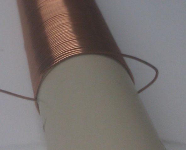
    The idea was that the word PVC refers to the coils being air-core and wound on pvc tubes, plastic tubes, like the ones used for wiring in a house. Like this coil:


    There may be a little problem, though, which is that the ratio between longitudinal and transverse propagation speed is not pi/2 by definition in the case of coils, as I posted in the Eric Dollard thread:

    Originally posted by lamare View Post
    You have to let go of seeing a coil as consisting of individual windings when thinking about these kinds of things. For example, the Joule-thief / SEC exciter circuits (with air core coils) work on frequencies in the order of 1 to may be 30 MHz, with wavelengths in the order of 10 to 300 meters, way more than the length of the used coils. So, these waves do not "see" the individual coil windings. They "see" the coil basically the same as an antenna consisting of a (meta) material in which the propagation speed of the wave is considerably slower than the propagation speed in air or any "real" material such as a copper tube.


    As far as I can tell, in "real" media the propagation speed of longitudinal dielectric waves is always pi/2 times the speed of that of transverse waves, irrespective of the medium. So, if you make an antenna out of copper, you can calculate with this pi/2 ratio between the longitudinal and transverse propagation speeds.


    The interesting thing is that for straight wire resonances, a 1/2 lambda longitudinal wavelength corresponds to 3/4 lambda transverse wavelength:

    pi/2 * 1/2 = 0,785398163
    multiply that by 4/3 and we get: 1,04719755

    So, whenever one of the two waves is in resonance, the other one is almost completely supressed!

    In other words: with straight wires, be it copper or the mantle of dielectric filled coax cable, you get this pi/2 ratio between propagation speeds and distinct resonance modes, whereby either one of the two wave modes is very dominant, because when one mode is in resonance and therefore amplifies itself as a standing wave, the other mode is supressing itself because it is almost completely out of phase.


    Another important question is: does this pi/2 ratio also apply to coils?

    In the "Oscillating Current Transformer" Eric talks about the importance of the width to height ratio of a coil:
    Tuks DrippingPedia : The Oscillating Current Transformer

    First of all, he says that the velocity of propation is 1 / sqrt( L_0 * C_0 ) {eq. 5}, whereby the distributed capacitance C is a function of the length to diameter (or height to diameter h/d) ratio, while the inductance L also depends on the coil height and diameter as well as on the number of turns. But the formula for the dependence of C and L on the h/d ratio is different, so by playing with the h/d ratio, you can play with the ratio between L and C.

    In other words: the ratio of L/C is a function of h/d, a function the geometry of the coil. According to Eric, you get a minimum capacitance when the h/d ratio is equal to one.

    Now the formula for the propagation speed of 1 / sqrt( L_0 * C_0 ) of course gives the propagation speed of the normal, transverse waves, which have both a magnetic and a dielectric component. The longitudinal dielectric wave, however, propagates without magnetic component and therefore primarily by means of space distributed capacitance.

    So, I think the ratio of pi/2 between the propagation speeds does not apply to coils, except for coils with a certain h/d ratio.

    So, now we have a new question: how do we calculate the ratio of the longitudinal vs. transverse propagation speeds in a coil??

    It may be a better idea to wind the sleeve coil directly on top of the main, long coil in order to get (almost) the same h/d ratio.

    Another idea would be to use bifilar windings.

    If you only wind the driving sections bifilar, you get a difference in distributed capacitance between your driving section and single wound section, which means that you can no longer just count the windings in order to determine where the nodes and antinodes will be in your standing wave. And you would also get different propagation speeds in both sections, so if you would want to do that, it may be a good idea to make the long coil a separate coil that is fed by one wire from the oscillator. In that case, you may want to mount the long section perpendicular to the oscillator section, so that the longitudinal waves, which propagates along the length of the coils, do not interfere with one another.


    If you would wind the whole coil bifilar, you end up with two connections at the other side. If you just connect those together and make sure you end at a voltage node, then you should be able to light a fluorescent.

    Update: Oops. Then the sleeve would probably not work anymore, because then the current is no longer forced into your sleeve coil, unless you leave the windings of the long coil that form the continuation of the open sleeve coil open at the emitter connection as well.....


    One would think that it shoud also be possible to somehow transform the longitudinal wave back into a normal, transverse wave and thus generate current. Tesla's TMT suggest that a pancake transformer can be used for such purpose. Having a bifilar wound coil gives you the opportunity to tap both of these windings at different points, which might give additional possibilities.

    Further insight in Gray's technology may also give further ideas for development:
    http://www.energeticforum.com/renewa...tml#post175036

    Essential for the operation of Gray's technology is that the oscillator which appears to exist in his CSET must have been producing impulses rather than harmonic oscillations, whereby you have an (extremely) steep rising edge and a gradually falling edge, the spikes John Bedini likes so much

    With these kinds of signals, there is a significant difference in the dE/dt during the (positive) rising edge and the (negative) falling edge, which is required in order to magnetize a coil (core). This is what I mailed Mark McKay some time ago on this:

    I think the trick is not so much in resonance per se as I thought before, but in having steep impulses traveling around your coil in the shape of waves and not so much currents trough the interior of the coil wire. The energy propagated by the fields themselves is much more than the energy released by currents, movements of electrons in a wire, and since their propagation speed is in the order of the speed of light, you can get an extreme impulse of dE/dt traveling around your coil.

    The problem with HF stuff trough a coil, without DC offset, is that you cannot magnetize a core, because the magnetization direction keeps on flipping back and forth. However, a DC "bias" component together with steep impulses on top, gets you extreme impulses of dE/dt (because of the high wave propagation speed), which is very interesting when we consider Maxwell's correction to Ampere's law:

    Ampère's circuital law - Wikipedia, the free encyclopedia

    So, you would need impulse waves with a steep rise time (extreme dE/dt) and a slow fall time (dE/dt much less), which would give you a netto magnetic field, whereby the magnetization can be extremely strong, because of this dE/dt wave propagates extremely fast compared to electron bound currents....

    I think that is the most basic principle, which explains why spark gaps are so interesting when operated in their negative resistance region, because there you have exactly this DC component combined with a device that can do fast switching and can therefore maintain a resonance mode whereby you have steep impulses (with the character sketched above) traveling along your coil.
    Update 2: The experiments by Stiffler and earlier Spice simulations ( Article:Free Electric Energy in Theory and Practice - PESWiki ) suggest that with Hartley oscillators using only coils (no external C in your tank circuit) you get a wideband signal, which appears to consist of the natural resonance frequency of your coil and higher order harmonics thereof. This suggests that these kinds of oscillators, with a strong feedback to the transistor, may indeed generate impulses rather than harmonic oscillations (under certain conditions?).

    However, that does not mean one can easily energize a coil with a coil-based oscillator, because the operation frequency thereof lies in the order of 1 - 30 MHz with long wavelengths expressed in meters. If this theory is correct, then Gray's device must have worked in the GHz range, with wavelengths expressed in centimeters, which is also suggested by the geometry of his CSET.

    It appears that longitudinal waves with these kinds of short wavelengths are capable of propagating circular around a coil, especially if the circumference of the coil is such that it is a whole number of longitudinal wavelengths, and are thus capable of energizing the coil as well as a core. Provided the waves are impulses, rather than harmonic oscillations.
    Last edited by lamare; 01-10-2012, 11:01 AM.

    Leave a comment:


  • kcarring
    replied
    @lamare

    Very interesting. In your diagram, i see that the sleeve coil's bottom terminates open, and while it's top seems to connect to the emitter, there seems to be an ambiguous part to the diagram in that right beside the word "PVC" -- to be exact, to the right of the letter "c", in "PVC" what is that line... is it wire ... or no?

    Thanks.

    When i wrap my head around exactly what u have here, I'll try it.
    Thanks
    Kyle

    Leave a comment:

Working...
X