Announcement

Collapse
No announcement yet.

Joulethief SEC exciter and variants

Collapse
X
 
  • Filter
  • Time
  • Show
Clear All
new posts

  • Slider2732
    replied
    Thanks folks

    @dR - There are some very different ideas coming forward from yourself and Lamare...that have reignited my own experiments.
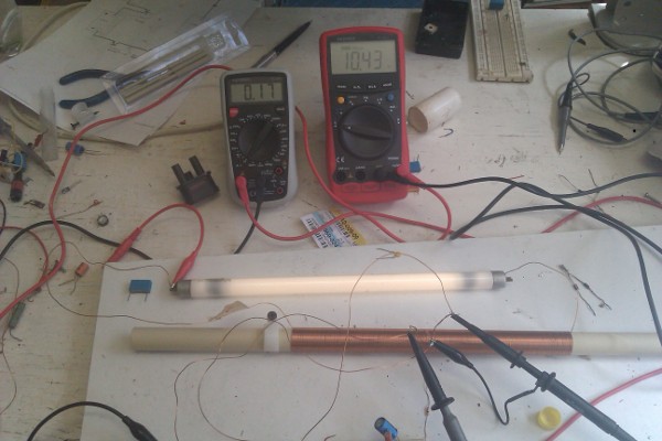
    Of interest might be that tower I used in the last video. You may have noted the secondary being the very scruffy 2 turn, but that it's sat way high up the tower. This is the same one as used in my Hoppity helicopter experiments and runs best for current conversion upside down. There are ferrite pieces to 1" down within the top, underneath those is some foam to stop it all falling to the bottom. For some reason, the output increased dramatically.

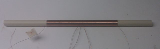
    One idea for room lighting using this sort of thing might well be introduced when we have funds to finish our livingroom. Being as the system needs only one wire, it would run neatly along the top of skirting boards all around the room. Then, any tube could be easily attached at any place desired, by a magnet or other means. No wall outlets needed, no mains voltage and easily possible to be a free soft lighting solution when using solar power and a 12V car battery
    Toranarod was talking of similar things in the Muller dynamo thread and it's weird how things mix together from different directions, same as MonsieurM mentioned at the top of this page.
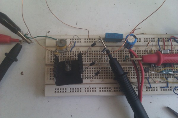
    Leave a comment:


  • dR-Green
    replied
    Originally posted by Slider2732 View Post
    And here's the resultant video - ‪Tesla tower - 1 wire 4ft fluorescent‬‏ - YouTube
    They run very nicely indeed for such a size !

    A new way (to me) of lighting such tubes was discovered too. A single wire to run, that also connects all 4 of the terminals.

    Excellent stuff, looking good

    I spent last night trying to stabilise the simple SEC and Tesla coil and beginning to play around with the 2nd coil. Strangely, the circuit will oscillate when I connect the transistor base to earth. I don't know if it works because of all the copper pipes and cables and water that's going all around the house and it's acting like a huge antennae, haven't tried it outside or on a separate earth connection to see if it still oscillates.

    So anyway, what I've come up with so far is a simple coil that fits inside the Tesla coil secondary. I started with 6mm diameter non magnetic stainless steel and copper rods and noticed that being too long (too close to the top of the coil and sticking out way beyond) or too close inside to the secondary winding it would bring the frequency down. Also current draw seemed to go up with no difference to the output. So I tried a coil of 17 SWG wire with what ended up as 4 turns after I got it small enough to fit inside the PVC pipe. If the coil is too low down inside the secondary it doesn't want to oscillate. I'll have to take pictures to make it clear what I mean, but basically the coil/wire has its own stand shaped into it, so unwinding turns allows me to have it higher inside the secondary. I think all that's unnecessary though. I think the key here is finding how much metal to use and how far along the length of the secondary it should go. So I reckon just a straight piece of wire exactly spaced inside the centre of the secondary PVC pipe should do the trick, cutting it off at the right length. And then one could put a small ball of tin foil on the end of the wire or something to make it a slightly better collector or fine tune it or whatever. Lots of things to try

    Leave a comment:


  • totoalas
    replied
    Originally posted by Slider2732 View Post
    And here's the resultant video - ‪Tesla tower - 1 wire 4ft fluorescent‬‏ - YouTube
    They run very nicely indeed for such a size !

    A new way (to me) of lighting such tubes was discovered too. A single wire to run, that also connects all 4 of the terminals.

    Leave a comment:


  • Slider2732
    replied
    And here's the resultant video - ‪Tesla tower - 1 wire 4ft fluorescent‬‏ - YouTube
    They run very nicely indeed for such a size !

    A new way (to me) of lighting such tubes was discovered too. A single wire to run, that also connects all 4 of the terminals.

    Last edited by Slider2732; 07-18-2011, 01:29 AM.

    Leave a comment:


  • Slider2732
    replied
    Glad it's working Lamare and it does bring up the use of small value capacitors on solid state Tesla coil circuits. Slayer had much luck with variable caps, the tuner type for old radios and I intend to do some more with those ideas too.
    The BD139 is great, I liked the one I had, until I blew it up with an insufficent heatsink

    Last night saw a salvage haul for me
    Next door were throwing out some 4ft long 36W fluorescent tubes and the tubes were just sat there on the grass after being refused by the collector truck. So by this evening I hope to have a video showing one of these monsters lit up

    Leave a comment:


  • totoalas
    replied
    Originally posted by lamare View Post
    Some time ago, I posted this:


    And I showed my coil:


    I now have this working:


    I used a BD139 transistor, and I can light a fluorescent tube of 8W nicely with it while drawing about 170 mA at about 10.5 V from the PS, but I don't seem to able to get any current out of the coil as I was aiming for, even though I haven't tried to charge a cap trough a diode bridge yet. Here's a close-up of the breadbord (right half unused):


    The trimming cap in the upper left of the picture is something like 100 pF, I guess. Just below, you see a 10 nF cap, which is not connected. The little yellow cap just below that one is connected between the feedback of the coil and the base of the transistor and is 390 pF if I read the fine-print correctly. The resistor from base to PS is 10k.

    What is interesting is that I get pretty high (BEMF) spikes at the coil connection to collector of the transistor, about 40V high and with a frequency of about 5 MHz, while at the coil connection to the couple cap to the base of the transistor, I get a more sine-like wave, with the same frequency, of course. The scale for the upper wave is 5V/div, the lower is 10V/div (corrected for using 10:1 probes) and the time scale is 0.5 us/div:


    I think this spike is important for getting the high voltage needed for lighting a fluorescent, because it contains many higher harmonics because of the sharp rising edge.

    Some more images and full size images of these: Dropbox - Photos - Simplify your life
    Congratulations Lamare finally work

    My suggestion how about this set up L1 Clock wise L3 on top of L1 ccw and L2 wrapping both coils L3 i think will pick up the enegy of L1 and prodce additional output( no connetion tothe base)
    cheers

    totoalas

    Leave a comment:


  • lamare
    replied
    Some time ago, I posted this:

    Originally posted by lamare View Post
    So, my conclusion for now is that all you need to do in order to get a current out of an oscillating coil is to make a coil a whole number of wave-lengths for the chosen frequency and to make sure the end of the coils are at a current hot-spot. Since, as you know, current and voltage have a phase difference of 90 degrees, it seems obvious that this is the way to do it:


    Since Slayer's long coil has a 384 turns in total and his short coil is 12 turns, we have 12 turns for 1/4 lamda/wavelength. Since the central tap is connected to the positive power supply, that point is a current hot spot, since it cannot be a voltage hot spot because it is connected to a fixed potential. So, every 24 turns away from the central tap, we have a current hot spot which are the points to try and tap current.

    So, if we make a long coil such that a whole number of wavelengths fit in it, and we make a tap in the middle for the positive power supply and two more taps for the transistor feedback and driving connections, we should be in business.

    In theory, L2 and L3 should be 12 turns if we take 180 turns for L1 and L4. Then, the tuning cap ( a few pF) should not be necessary. However, if you take 10 turns for L2 and L3 and add the optional tuning cap, you can tune the circuit for maximum output.
    And I showed my coil:

    Originally posted by lamare View Post
    Just finished winding my coil:


    I wound these coils on a 19 mm (3/4") electricity tube normally used for housing power wires.

    [...]

    The coil is wound with 0.5 mm wire, 180 - 12 - 12 - 180 turns. That's all for today. Hopefully we'll know if it works tomorrow, depending on time available.

    I now have this working:


    I used a BD139 transistor, and I can light a fluorescent tube of 8W nicely with it while drawing about 170 mA at about 10.5 V from the PS, but I don't seem to able to get any current out of the coil as I was aiming for, even though I haven't tried to charge a cap trough a diode bridge yet. Here's a close-up of the breadbord (right half unused):


    The trimming cap in the upper left of the picture is something like 100 pF, I guess. Just below, you see a 10 nF cap, which is not connected. The little yellow cap just below that one is connected between the feedback of the coil and the base of the transistor and is 390 pF if I read the fine-print correctly. The resistor from base to PS is 10k.

    What is interesting is that I get pretty high (BEMF) spikes at the coil connection to collector of the transistor, about 40V high and with a frequency of about 5 MHz, while at the coil connection to the couple cap to the base of the transistor, I get a more sine-like wave, with the same frequency, of course. (It may be the spikes here are blocked by the protection diodes). The scale for the upper wave is 5V/div, the lower is 10V/div (corrected for using 10:1 probes) and the time scale is 0.5 us/div:


    I think this spike is important for getting the high voltage needed for lighting a fluorescent, because it contains many higher harmonics because of the sharp rising edge.

    Some more images and full size images of these: Dropbox - Photos - Simplify your life
    Last edited by lamare; 07-17-2011, 12:11 PM.

    Leave a comment:


  • dR-Green
    replied
    Excellent info, thanks I finished winding my 2nd Tesla coil secondary last night which I started on thursday before I got sick, and that's wound in the opposite direction of the one I already have. So once I get the whole thing finished I can swap the secondaries around as I wish so then the primaries will be in the opposite direction etc, but it works nicely in the same direction at the moment, so I'd be interested to see the difference. The PVC pipes I've wound them on are as closely matched as I could get them in terms of where the winding should start and end, but how much copper has fitted and stretched and compressed or whatever in that space I don't know. I don't know about tuning coils so I've bought a frequency generator kit and my plan is to put that through a coil and look at it on a scope and see where the resonant frequencies are and I suppose just improvise.

    The LED in a glass of water sounds interesting I've just been playing with the trigger on the simple SEC, trying to come up with a simple coil arrangement as per Lidmotor's video but on a separate toroid or something. Looks like it's going to have to be somewhere on the HV/secondary wire

    Leave a comment:


  • Slider2732
    replied
    There is a world of difference in three areas for all this...the transistor, the tower and the primary winding.
    On a good tower at 12V - A heatsinked 2SA1020 or A966 or MSPA06 perhaps will create plasma of 1" and light a house bulb to near full brightness from a few inches away (especially when the bulb is upside down and above the tower).
    On the same circuit and tower, an S9018 might flicker an LED when hard wired directly into the inside contacts of the LED, in a vacuum, using car jumper cables !. They are however fine for low power signal use in battery radios.
    Common as muck 9014's, C945's and 3904's are perfectly adequate even at the higher voltages (with heatsink) to test anything out, destroy a few and have no worries about replacing them. KN2222's are better than regular 2N2222's, both are well above average.
    Jonny's pop bottle tower is very very good when wound with approx 22 gauge wire. My tiny towers that use less than hair thin wire are great too, but tedious to wind. In between, about 1000 turns of 26 gauge on a 2" diameter 10" high section of thin plumbing pipe will be good.
    2 winds of a much thicker gauge never fails for me as a primary. Close coupled to the tower or twice the diameter of the tower.
    If your tower wind is clockwise then your primary needs to be anti-clockwise. Using a NPN transistor, the positive wire goes to the top of the primary, the Collector to the other end at the bottom. That's the same for any arrangement, including raised pancakes.
    A raised pancake coil fitted inside the tower can improve performance, but is not really any better for power out in most testing cases than an easier to wind couple of turns.
    If using a toroid joule thief type of method, then you can wind the toroid with one continuous wrap of wire. Scrape the middle turn and that's your positive power connection. For some reason that works just fine.
    CFL tubes of 18W and 2ft length nearly always will suddenly burst to life when right next to a tower and then can be drawn around to some distance, it's that firing up that can confuse as it has to be near a tower. CFL house bulbs don't need that initial close proximity. Neons will slightly glow and increase in brightness the nearer they get to the tower, same with LED's. Water works well btw, stick an LED on an AV plug in a glass of water and watch the thing light up to impressive ranges.
    3 turns and power drops, 1 turn and power drops. 8 or 12 or something and we're looking at trying to hit resonant frequencies of a different nature and normally when pairing two towers...which means mathematics, which means I don't do that lol. Some say to match the copper used, primary as secondary to have the same amount of copper used within each. However, even the braid insulation of coax TV cable can also be used as a primary and works. Much opens up when experiments show the ranges to use, that do come naturally over a while

    Just some simple pointers, I hope they may help. It sounds like you may be having a transistor problem more than anything.
    Last edited by Slider2732; 07-16-2011, 10:44 PM.

    Leave a comment:


  • dR-Green
    replied
    It works It was just a matter of swapping the trigger polarity, and the stupid thing is I automatically did that without even thinking about it to get it work as an SG Oh well.

    Anyway, from what I've seen so far the simple SEC seems to perform much better. It's a little erratic in terms of input power, but I'm getting a much better output than the joule thief SEC. I'm having to use 12v+ to light a neon at very close range, and a 4W fluorescent won't light at all. It also doesn't like the Tesla coil. Using the simple SEC at 6v 20mA, the fluorescent lights 1 inch away from the toroid [edit] <at the top of the Tesla coil> and will get dimmer until it goes off 7 inches away, and a neon lights easily. It gets more impressive with a higher input voltage, but the current draw goes up to 200mA with no load, and down to about 60mA when loaded.

    So I'm off to play with different things now Thanks for the help Nick, Slider and Johnny I'll post back here after I've tried a few things
    Last edited by dR-Green; 07-16-2011, 10:12 PM.

    Leave a comment:


  • dR-Green
    replied
    Originally posted by jonnydavro View Post
    Cut the wire at the fold and connect one of the cut ends to one of the starting wires so it is end of coil to start of coil.This will be your Battery + connection.
    I think this is where I've been going wrong. I got ill thursday night so I haven't been able to try anything yet, but I suspect I have the "trigger" winding connected the wrong way.

    Thanks for the info, I'll swap the connections shortly and post back the results.

    In the meantime I came across these videos and they've given me a couple of ideas, like Lidmotor using the open ended coil wire. That's a better idea than my aluminium around the Tesla coil secondary so I might come up with some sort of arrangement along those lines, or using a toroid feedback as I've seen in one of your videos, something like that. I get a better output (using the simple SEC circuit) with the Tesla coil than I do with the 6kV trigger transformer so I'd like to keep experimenting with that.

    &#x202a;Jonny Lidmotor Exciter from user Lidmotor&#x202c;&rlm; - YouTube

    &#x202a;Self Resonating Powering Circuit for HHO cell&#x202c;&rlm; - YouTube

    But all these problems are helping me to understand the basic circuit and how it's supposed to work, so hopefully that will be useful once I get things going Thanks for all your help so far.

    @NickZ: Thanks for the suggestion, but I've already had to try as low as 1.5v just to be able to try different resistances because the current draw was just getting too much and I didn't want to pop things. I've also swapped the 4A power supply for a 500mA bench power supply to try and limit the damage. But as I was telling Johnny I suspect my trigger winding is back to front If it's not, well I'll get back to you lol. Thanks

    Leave a comment:


  • NickZ
    replied
    dr- Green:
    It may be that the transistor base is getting too much juice to it and just blinks when you disconnect it. Try less voltage to see if the led will light. A pot on the base of the transistor base may help.

    Leave a comment:


  • jonnydavro
    replied
    @dR-Green.Hi I re-read my previous post and can see that i am only adding to the confusion.Try this.Get a 2' lengh of 0.6mm maplins bell wire and fold it in half so you have two wires.Wrap these two wires 5 times around your cfl toroid.Cut the wire at the fold and connect one of the cut ends to one of the starting wires so it is end of coil to start of coil.This will be your Battery + connection.
    I just did this with another cfl torroid and it worked so hopefully yours will too.
    Here is a good joulethief tutorial which may make thing clearer.
    The Joule Thief!
    I think the output voltages of the simple sec and joulethief exciter circuits would be comparable.
    I have had a circuit for a trigger coil led driver sitting on a breadboard for months now and you may find it useful.Here is a circuit diagram and vid.It will run down to 0.3v and you can use high input voltages on it too so quite versitile and a good joulethief alternative for a torch.Happy experimenting.Jonny
    &#x202a;Led driver&#x202c;&rlm; - YouTube

    Leave a comment:


  • dR-Green
    replied
    Originally posted by jonnydavro View Post
    Hi dR-Green.Nice pics The joulethief exciter circuit you have been trying to get going was my first exciter variant and was was the catalyst for starting this thread.Here is the vid and circuit diagram for reference.

    &#x202a;Joulethief SEC Exciter-wireless energy transfer.&#x202c;&rlm; - YouTube
    I still have this circuit on a breadboard and it works great and like i mentioned in a previous reply,exciter circuits can have vastly different characteristics and this one is no exception.First of,it is a very stable circuit as the feedback to the transistor is hard wired and not effected by loading.Also the operating frequency is much lower than the simple sec,slayer exciter etc so there is an audiable squeaking from the output tray when touched so there are some interesting things to see here but as far as i am aware,i don't think anyone replicated this so i may have the only one,same thing with my bedini exciter but hopefully i can help you get yours going.
    The first thing i will say is stick with the small cfl torroid.I tried larger and my amp draw went crazy.We want this circuit to run on up to 17v without using large base resistors so try to stick with a close rep on this or you will have problems.Use the 0.6mm solid core bell wire from maplins.Cut two small lenghs about 12" long and wrap like this.With the torroid facing you feed one wire through the hole away from you and do 5 turns starting at the bottom of the torroid..Then feed your other wire into the torroid from the opposite direction of the first and starting at the bottom again,wind 5 turns inbetween exhisting turns.Trim your wires off so you have 4 wires about 1 " long.Connect the two end wires,this will be the battery + connection.The other two wires will be your base and trigger coil connections as in the circuit diagram.
    Test this coil out as a standard joulethief first to see if it will light a led.
    The 4.7uf cap is vital in the joulethief exciter and it will not work without it.
    You can use a larger variable pot if you don't have a 1k but don't have an led accross the collector emitter normal joulethief style.
    Hope this helps.Jonny.
    Thanks Johnny I was going to say "what if the joule thief doesn't light the LED?", but reading what you said about the toroid just made me think of something... Is the polarity of the windings important? I don't quite understand what you mean from the description, I always get confused when someone tries to explain in words how to wind a coil, so I suppose the only thing I haven't tried and should have been one of the first things is to change the polarity of one of the windings, like changing the polarity of the trigger in a Bedini circuit?

    Does the joule thief SEC also deliver a higher voltage across the trigger transformer than the simple SEC?

    Thanks for the help

    Leave a comment:


  • jonnydavro
    replied
    Hi dR-Green.Nice pics The joulethief exciter circuit you have been trying to get going was my first exciter variant and was was the catalyst for starting this thread.Here is the vid and circuit diagram for reference.

    &#x202a;Joulethief SEC Exciter-wireless energy transfer.&#x202c;&rlm; - YouTube
    I still have this circuit on a breadboard and it works great and like i mentioned in a previous reply,exciter circuits can have vastly different characteristics and this one is no exception.First of,it is a very stable circuit as the feedback to the transistor is hard wired and not effected by loading.Also the operating frequency is much lower than the simple sec,slayer exciter etc so there is an audiable squeaking from the output tray when touched so there are some interesting things to see here but as far as i am aware,i don't think anyone replicated this so i may have the only one,same thing with my bedini exciter but hopefully i can help you get yours going.
    The first thing i will say is stick with the small cfl torroid.I tried larger and my amp draw went crazy.We want this circuit to run on up to 17v without using large base resistors so try to stick with a close rep on this or you will have problems.Use the 0.6mm solid core bell wire from maplins.Cut two small lenghs about 12" long and wrap like this.With the torroid facing you feed one wire through the hole away from you and do 5 turns starting at the bottom of the torroid..Then feed your other wire into the torroid from the opposite direction of the first and starting at the bottom again,wind 5 turns inbetween exhisting turns.Trim your wires off so you have 4 wires about 1 " long.Connect the two end wires,this will be the battery + connection.The other two wires will be your base and trigger coil connections as in the circuit diagram.
    Test this coil out as a standard joulethief first to see if it will light a led.
    The 4.7uf cap is vital in the joulethief exciter and it will not work without it.
    You can use a larger variable pot if you don't have a 1k but don't have an led accross the collector emitter normal joulethief style.
    Hope this helps.Jonny.
    Last edited by jonnydavro; 07-14-2011, 05:35 PM.

    Leave a comment:

Working...
X