Announcement

Collapse
No announcement yet.

Joulethief SEC exciter and variants

Collapse
X
 
  • Filter
  • Time
  • Show
Clear All
new posts

  • lamare
    replied
    Just tested my coil. So far, no luck. When I switched on the power, it drew much more current than my multi-meter was happy with

    Since I used that multi-meter for transistor testing too, I'm out of Hfe meter, which is not nice.

    Anyway, I did get some oscillation for some time. Enough to light a neon bulb, but that was all so far.

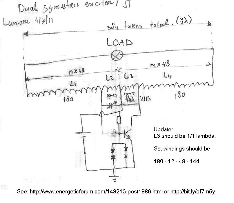
    And that just when you expect interesting results, because I really think this will work very well, because you get voltage multiplication, while at the coil ends you have the same current as at the point connected to the collector of the transistor. So, if I understand this right this time, we should see at least 8 times more energy out than we have to put in to keep the thing oscillating.

    Anyway, there's always another day.....

    Leave a comment:


  • Slider2732
    replied
    The Slayer circuit you linked to over at BrOkenman's place is correct enough and works great. Now, what to do about that hot transistor situ and no output ?
    Well, replace the diode that goes from negative supply to the Base of the transistor with a common or garden red LED. The LED connects the wrong way around, same as the diode did. The effect on your circuit is the same, BUT, you get to see how well your coil arrangement is working The brighter the LED, the stronger the wireless field and how well it is all working.

    Voltage to a 2222A or MPSA06 or practically anything else can be down to 1V or thereabouts and you'll still get a wireless field. At 3V, no transistor will explode or self combust. A wireless field ought to be at least a few inches and you'll gain much by altering the turns on the large fat few wind primary coil. If you have a fine gauge of about 30 for the secondary, then the primary can be speaker hookup wire (thick gauge 18ish) of just 2 turns. Make sure the primary and secondary are wound in opposite directions.
    To test the field, an LED on the end of a 2 diodes splitter (AV plug) is the way, with about 6" of thick gauge wire hanging off the end of the diode join point. But, crucially, the strength of brightness of the LED that sits across the transistor is the major guide toward power being derived. If the LED doesn't light at all, then swap the connections to the primary. Once the LED comes on, yer home and dry.
    Increasing the voltage may result in the need for a heatsink. Well, it will for sure when driving above 4.5V normally. Can make one by supergluing the transistor to a large chunk of metal. Or by inserting it into the spaces in a fin type heatsink, or by bending thin aluminium sheet around it.
    I have an A966 PNP that's been through some hours of experiments at 12V, that one sits between fins of a heatsink. I used pliers to open out 2 fins and then closed them back up by squeezing with the pliers again. It runs at 12V all the time and is great for the plasma speaker stuff.

    Here's that transistor Mega-Test I did
    Attached Files
    Last edited by Slider2732; 07-05-2011, 08:10 PM.

    Leave a comment:


  • Farmhand
    replied
    Hi 7, I'll post the other circuit, the SG3525 one over in the other thread too, shortly, the one you showed me to start with but I built second with all the terminals.

    Thanks again for helping me with those circuits too 7imix, much appreciated.

    Leave a comment:


  • 7imix
    replied
    Originally posted by dR-Green View Post
    Thanks Farmhand. I've slowly been going through this thread in between getting annoyed at nothing working but I've only made it to page 2 so far I just bought a load of transistors off ebay in the last few minutes though, 40x BC182, 25x 2N2222, and 100x MPSA06, that last one costing me £6.66 so I hope that's a good sign Once I get SOMETHING working and plenty of spares then I can get playing with different things. The frustrating part at the moment is I can't even get anything working because either I don't have the right parts or the parts I have won't work. I have a small Tesla coil here which I want to play with, and I'll be making a mirror image coil sometime soon, so this seems like a good place to start. That circuit in your Magnifying Transmitter thread is a little complex for the moment
    I highly recommend building that pwm circuit. It's really not too hard and gives a huge amount of flexibility in driving various different coils in different ways.

    Leave a comment:


  • dR-Green
    replied
    Thanks Farmhand. I've slowly been going through this thread in between getting annoyed at nothing working but I've only made it to page 2 so far I just bought a load of transistors off ebay in the last few minutes though, 40x BC182, 25x 2N2222, and 100x MPSA06, that last one costing me £6.66 so I hope that's a good sign Once I get SOMETHING working and plenty of spares then I can get playing with different things. The frustrating part at the moment is I can't even get anything working because either I don't have the right parts or the parts I have won't work. I have a small Tesla coil here which I want to play with, and I'll be making a mirror image coil sometime soon, so this seems like a good place to start. That circuit in your Magnifying Transmitter thread is a little complex for the moment

    Leave a comment:


  • Farmhand
    replied
    Hi dR-Green, I haven't had much success with these self oscillating circuits myself. But from what I think I have picked up the 3055 transtors won't work. There is a list done by slider back in this thread, he tested a lot of transistors. I managed to get my coils oasillating with the joule thief circuit using a MPSA06 transistor but i've put it aside for now to do other things. I didn't really have time to learn much yet. I did try some other transistors TIP 42 and 3055 but no dice for me either.

    It is a shame that the same effect can't be done with bigger transistors and more power. Seems like the only one's that work are the very small one's.


    Cheers

    Leave a comment:


  • dR-Green
    replied
    Well, I can't seem to get any of this to work. I found some schematics here, and I've made the 6v circuit because all the parts were immediately accessible, almost

    Wireless Electricity - SEC Circuit build

    Only difference is I'm using a 2N3055 and 1N4001 diode. Using a 9.6v bank of AA batteries which have just over 8v in them, didn't see any point in using bigger batteries or a power supply or specifically building the 9v+ circuits (yet) because the damn thing just won't oscillate and I don't have all the components at hand, so, well to hell with searching for hours for parts to build something that won't work, so I made the simpler version. Everything I try, all I end up with is a hot transistor. And the thing doesn't even work at all when I have an ammeter connected, not even the privilege of a hot transistor, so the only indication I have of anything going on is either the scope showing the constant input voltage, or the smell/heat coming off the transistor.

    Leave a comment:


  • lamare
    replied
    Just finished winding my coil:


    I wound these coils on a 19 mm (3/4") electricity tube normally used for housing power wires. In order to keep the windings in place, I just drill a hole trough the tube and stick the wire trough, as you can see in this close-up:


    The coil is wound with 0.5 mm wire, 180 - 12 - 12 - 180 turns. That's all for today. Hopefully we'll know if it works tomorrow, depending on time available.

    Full size images: Dropbox - Photos - Simplify your life
    Last edited by lamare; 07-04-2011, 08:08 PM. Reason: Dropbox thumbnails not publicly accessible.....

    Leave a comment:


  • dR-Green
    replied
    Originally posted by Slider2732 View Post
    dR, I would suggest Freecycle and an advert for 'broken electronics'. People are always throwing stuff out. Even a TV discarded on the roadside is one heck of a resource. A drive around this evening while watching fireworks and you might be able to replace everything that's blown up ! (depends on the area you live in though and if in the USA).
    I've never bought a transistor, got too much old junk to even think of that lol.
    Darlingtons have been poor performers for me. I don't see why they should be, but have been.
    I like your style I was just looking through my dad's box of components and I managed to find another 2N2222. But what's also frustrating/disappointing about this is that jonnydavro was using a 2N2222, but mine won't work. I know it CAN work because it did briefly with the BC182, so I see no reason why I shouldn't be able to get it going with the 2N2222 I have yet to try it with the joule thief SEC circuit though so we'll see shortly, and I haven't tried the Darlingtons yet, that will be done within a few minutes too. On the Darlingtons though, the only place I've ever tried it so far was on my SSG, and it didn't like that at all, just kept coming to a halt. So I'm hoping it will be a bit more successful in this circuit

    [edit] On second thought, if we are using identical transistors in the Darlington pair, wouldn't it defy the point? You'd still need the same level input to trigger the first of the pair as if you were just using one of those transistors? So wouldn't we need a transistor with a higher gain to switch the higher power transistor that has lower gain, or use a smaller one to trigger the bigger one?
    Last edited by dR-Green; 07-04-2011, 07:14 PM.

    Leave a comment:


  • Slider2732
    replied
    I like the thoughts lamare...and, makes complete sense when we look at the importance of 1/4 waves in many areas.

    Much of the guesstimate tunings is derived from the simple circuits by looking at the LED, that normally sits across the transistor in Slayers circuit and derivations. Where it becomes brightest for whatever primary coil you have, is the best for results from the setup.

    dR, I would suggest Freecycle and an advert for 'broken electronics'. People are always throwing stuff out. Even a TV discarded on the roadside is one heck of a resource. A drive around this evening while watching fireworks and you might be able to replace everything that's blown up ! (depends on the area you live in though and if in the USA).
    I've never bought a transistor, got too much old junk to even think of that lol.
    Darlingtons have been poor performers for me. I don't see why they should be, but have been.

    Leave a comment:


  • dR-Green
    replied
    I'm having trouble getting this thing working. I managed to get the simple circuit working last night with what I assume was a BC182, it's old and the casing is too corroded to tell, I played about with lighting some fluorescent lights for about 10 seconds then I think I killed it by touching the aluminium trays together. The only BC182 I could find is now dead. Tried a 2N2222, this time making sure not to touch the pans, nothing at all. 2N3055, nothing. 2N5320, nothing. Same story with lots of others, the ammeter doesn't even budge.

    So I tried the SEC joule thief thing within the last few minutes, using a 2N3055 because I don't want to destroy the only 2N2222 I have, 700mA draw, no effects to be seen whatsoever. Tried two different bi-filar toroids, though I did make them to use with solid state SG circuits so they're not the smallest of coils/wire. The circuit is apparently just shorting through the transistor and causing heat and nothing else?

    I'll be trying a Darlington pair configuration to see if I can increase the gain to get the simple circuit working with a 2N3055, but otherwise this is very disappointing. Now I'm going to have to wait a few days for deliveries off ebay if this doesn't work
    Last edited by dR-Green; 07-04-2011, 05:15 PM.

    Leave a comment:


  • totoalas
    replied
    In theory, L2 and L3 should be 12 turns if we take 180 turns for L1 and L4. Then, the tuning cap ( a few pF) should not be necessary. However, if you take 10 turns for L2 and L3 and add the optional tuning cap, you can tune the circuit for maximum output.

    Have fun if you want to experiment with this! [/QUOTE]


    Thanks Lamare for the info and the results your sharing

    My 12 1 mA 2 inches dia coil used 80 turns c and ccw with 9 t L2 connected t Mpsa06
    After i dismantled for other tests .... cannot replicate the same result
    I think this is were the fun begins as you say

    cheers

    totoalas

    Leave a comment:


  • lamare
    replied
    Some time ago, I posted an analysis of Kapanadze's device and an idea how one may go about making a solid state version:

    http://www.energeticforum.com/115135-post1341.html

    Because of my disappointing results when trying to use a counter-clockwise sliding coil over the long coil of my variation of Slayer's circuit, it looks like you need a pretty tight coupling between the coils. In my setup, I did not wind the short coil on top of the long one, but next to the long one, so my setup has a much weaker coupling between the coils, which is probably why I cannot light a fluorescent tube with my setup.

    So, when I looked back to my idea of how to make a solid state Kapagen-like device (link above) and given that Kapanadze drives his coils directly and not trough a transformer, I think this may be a better design for a solid state Kapagen device:


    Looking at this, it occured to me that Kapanadze's spark gap draws a considerable amount of current from the coil, while he has a 3/4 lambda CCW coil at the left, and a 1/4 lambda CCW coil at the right:

    Update: This is not completely accurate. The number of turns given leave room/variation for 20 turns in total, significantly more than the 12 turns that represent 1/2 lambda/wavelength and also more than the 18 turns that represent 3/4 lambda. When I posted the analysis linked above, I thought you needed an odd number of 1/2 wavelengths in total, while now I come to the conclusion you need a multiple of full wavelengths over the total length of the coils in series in order for the terminals you want to tap the power from to be in phase current-wise.


    So, while I first thought he wound these coils counter-clockwise in order to kill the magnetic component, I now think it is because the two shorter coils are connected in the opposit direction compared to the main coil, so he apparantly wound these short coils CCW in order to prevent killing the magnetic component! Oops.

    So, my conclusion for now is that all you need to do in order to get a current out of an oscillating coil is to make a coil a whole number of wave-lengths for the chosen frequency and to make sure the end of the coils are at a current hot-spot. Since, as you know, current and voltage have a phase difference of 90 degrees, it seems obvious that this is the way to do it:


    Since Slayer's long coil has a 384 turns in total and his short coil is 12 turns, we have 12 turns for 1/4 lamda/wavelength. Since the central tap is connected to the positive power supply, that point is a current hot spot, since it cannot be a voltage hot spot because it is connected to a fixed potential. So, every 24 turns away from the central tap, we have a current hot spot which are the points to try and tap current.

    So, if we make a long coil such that a whole number of wavelengths fit in it, and we make a tap in the middle for the positive power supply and two more taps for the transistor feedback and driving connections, we should be in business.

    In theory, L2 and L3 should be 12 turns if we take 180 turns for L1 and L4. Then, the tuning cap ( a few pF) should not be necessary. However, if you take 10 turns for L2 and L3 and add the optional tuning cap, you can tune the circuit for maximum output.

    Have fun if you want to experiment with this!


    Update: For more information about the negative resistance properties of a spark gap (oscillator) as used in the Kapagen device, as well as references to a modern negative resistance device known as a "lambda diode" as used in modern oscillators, see this part in my 'article' over at Pes:
    Article:Free Electric Energy in Theory and Practice - PESWiki
    Note that oscillators using a negative resistance device do not need a feedback signal as needed by a transistor operated device. In other words: with a spark gap or lambda diode you can oscillate a single coil, while for single transistor oscillators you need some form of feedback signal to the base of the transistor.

    Update 2: Link mentioned in the image about coil windings: http://www.energeticforum.com/148213-post1986.html
    Last edited by lamare; 07-20-2011, 08:58 AM.

    Leave a comment:


  • lamare
    replied
    Phi heterodyning

    I posted an interesting article I found about "Phi heterodyning" here:
    http://www.energeticforum.com/146432-post105.html

    I think the star-shaped coil is a very interesting candidate for experimenting with that, should anyone feel like trying something extra-ordinary...

    Leave a comment:


  • Slider2732
    replied
    That's great to hear you two fellows are right there
    I built up the circuit yesterday and the old bugbear of no test equipment showed through spectacularly - nothing happened
    Duty cycle and frequency were twiddled with, but all the while nothing of anything was going on. The coil was a mini Tesla tower though and that's perhaps why. Also, the NE555N was a salvage many years ago from an old circuit and had been soldered up before this experiment...I need to run that as a 1Hz flasher to make sure it actually works !
    The phrase I quoted to myself was 'do it properly or not at all'.

    Leave a comment:

Working...
X