@Xee2
Thanks for the formulas and the comparison. I'll run these coil numbers.
Thanks again
-
pancake coil vs. solenoid
@ Jiffycoil
You have probably already done this, but I compared the inductance of a pancake coil and a solenoid (both using the same length of wire) and it seems that the pancake coil produces about 50% more inductance than a solenoid. More inductance equals more voltage. I guess that is why they work so well.
equations at:
Wheeler Formulas for inductanceLeave a comment:
-
Hi totoalas, I've been a little bit distracted, I should have mentioned that a larger cap would be ok it's just to test, I thought with a small cap if the effect is weak or strong or non exsitant it will be easy to tell.
Thank you.Leave a comment:
-
Puck Lights
Hi Jiffy
nice output from your puck lights
My replication of your puck coil
@ 14 volts tip 42c and ! k resistor 460 ma
the end of the pancake L1 had a half cm plasma along the wires touchng anything metal burned the loop coil at the end and a different smell of the plasma when i chaned to 1 meg resistor the output was tamed and no more blue output 140 ma
cheers
totoalasLeave a comment:
-
Originally posted by woopy View Post
@Beautiful work Woopy,
You have spent some time winding many coils lately. The information gathered form your experiments helps us all.
@Xee2
I need to wind a coil like the one you posted. It will be good to see how they work. Thanks for posting that.Leave a comment:
-
simple apparatus to detect the right point on coil
Hi all
always working on all those coil and the Slayer Xter i tested a good and simple way to find where the coil is at it's best.
An electric testing screwdriver that you hold in your finger and you simply go up and down the coil and you see exactly where is the best working point. The neon light work also but much less precisely and the led on AV is very difficult to judge objectively and my scope probe is totaly unusefull as the trace completly crazy and out of range.
Just for info my conical Slayer coil (L1) can be easily excited by a a pancake coil underneath and give also great results. So perhaps that a conical coil has also the same advantage than the flat pancake . Just to think
my 2 cents for today
LaurentLast edited by woopy; 01-26-2011, 10:47 AM.Leave a comment:
-
Hi totoalas, If somebody could try a simple set up similar to this for a very quick test to see if an exciter will charge the cap. Any old slap up arrangement will do, maybe somebody has already done a plate charge test.
I forgot to draw it but a diode may be needed between the plate and cap. Or a bridge.

ThanksLeave a comment:
-
Voltage Swapper
http://www.energeticforum.com/115329-post16.html
I'll try to make a drawing later tonight, I would like to try this as well with a simple exciter circuit, as simple as possible so I can get some results quickly as an indication. I really don't know if it would work. Maybe someone with an exciter could try a small experiment soon ?
Here's the vid- YouTube - AlternateFarmhand1's Channel
I'll try to make time tommorow to demonstrate the function of the battery swapper on a couple of good batteries, I have a load dump set up but it's only two fans, if the sun is out they might get fried if they can't handle 18 volts.
Quote from Farmhand above
Hi to all
there is a request from this thrEAD if we can try his circuit on the Slayer
Any input is welcome
cheers
totoalasLeave a comment:
-
I posted these results previously, but I am re-posting for comparison with the pancake coil circuits. I have not made a pancake coil to compare the two directly. But, from my notes and posts that others have made, this design seems to have similar performance to the pancake coil and is easier to make. However, I found it was difficult to find a good turns ratio for the coil. Maybe it is easier to get the pancake coil design to work.


 Last edited by xee2; 11-06-2010, 12:58 PM.
Leave a comment:
-
Jiffy Coil a la CD Wireless
[IMG] Uploaded with ImageShack.us[/IMG]

Uploaded with ImageShack.us

Uploaded with ImageShack.us
[IMG] Uploaded with ImageShack.us[/IMG]
Hi To All
Jiffy / Slayer thanks again for the pancake design
@14 v dc 460 ma very strong plasma and 10 cm wireless transmission
29 awg 3mm thick on a cd case coiler 10 cm dia
1.5 mm stranded plastic insulated 12 cm outside dia ( on a cd) 6 turns
cannot touch the output of L1
TIP 42c NPN 1M transistor
I think we can still reduce the coil to a coin????????????
cheers
update:
[IMG] Uploaded with ImageShack.us[/IMG]
1 aa cellphone charger L2 12 t 2.5 mm plastic insulated stranded 130 ma with 1 M resistor
With 689 ohms 250 ma with 8 w fl lamp load
totoalasLast edited by totoalas; 11-07-2010, 12:07 PM.Leave a comment:
-
Transformer / Exciter circuit with Kapagen coil
Hi all,
This idea of bifilar wound coils by Tesla, which appears to have been taken a step further in the Kapagen device appears to offer interesting possibilities.
If indeed you can create pure electric, longitudinal oscillations without magnetic fields in coils which are wound in opposit directions on top of one another and indeed this gives a voltage gain, then it is probably possible to make an amplifying transformer like this:
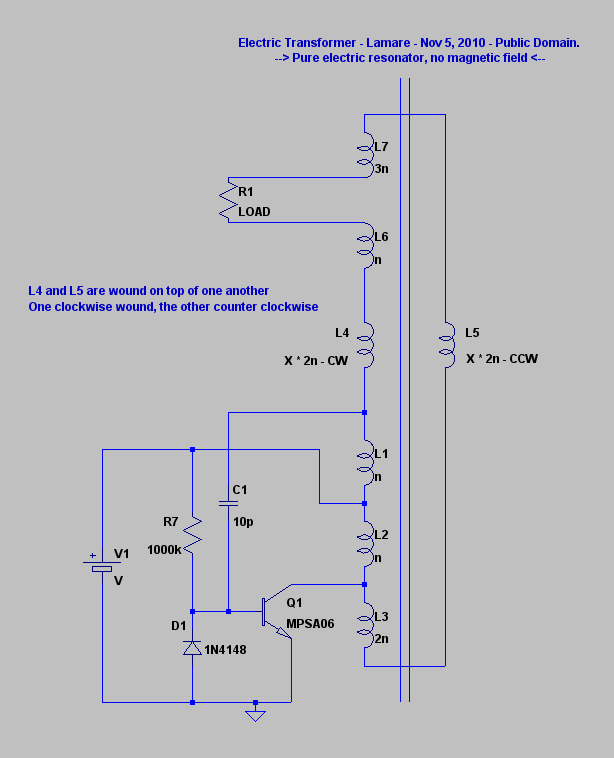
All coils are wound on a single air core, as are the other exciter circuits.
Around L1 and L2, you have a pretty standard exciter circuit, which determines the oscillation frequency. For a typical exciter, n would be 12 or so.
Because we want L4 and L5 to be resonating in phase and we get a 180 degree phase shift across L1 and L2, we add another normal wound coil on top of L1 and L2, with 2n turns, so we get a full wave across L1, L2 and L3. So, the upper terminal of L1 will be in phase with the lower terminal of L3. We drive each of the counter-wound coils from one of these.
So, we get a normal EM oscillator across L1-L3, which is both connected and capacitively(!) coupled to the counter wound coils and thus drives these into resonance at a higher harmonic of the longer coils.
Since the counter wound coils are supposed to cancel the magnetic component, we want a voltage hot spot at both ends of the coil, so we want it to have a length of multiples of a half wave, so X * 2n turns. However, the coil on top has a slightly bigger diameter, so you may need a couple of turns more on the one on top. (unless you really wind them bifilar, but then you probably need some extra turns, given the picture I posted before: http://sites.google.com/site/teslanichelson/Helix.jpg - oops, that won't do when you want one CW and the other CCW )
)
Now if this works as expected, we get a significant voltage gain across these counter wound coils. This comes with a price attached, though, cause these coils cancel out the magnetic field and therefore cannot give you much current. (update: hmm, this may not be intirely true, cause even though the magnetic fields cancel, you can still have currents, given the Kapagen device. It's probably more that no energy gets "stored"/"lost" in creating a magnetic field that you don't really need when you have an electric field to drive your charge carriers and thus give you a current.)
So, at the opposite side of the transformer, we do the same thing as with the driving coils, so one coil with n turns and one with 3n turns, so we end up with a current hot spot between L6 and L7, which are normally wound and should therefore be capable of delivering current.
As for the load, I think this can be either a resistive load, or a capacitor with a rectifier bridge, which can deliver DC.
Of course, I haven't built this (yet) - just got the idea this afternoon -, so it may or may not work. If it does, great. Then I'm glad this cannot be patented anymore, cause it's public knowledge. If it doesn't, well, too bad, nice try.
So, YMMV, and whatever you may want do with this is fine with me. Just make sure to have fun doing it!
-- Arend --
To avoid confusion: all coils are single-layer wound, tightly next to one another (on top of one another) in the order shown except the ones shown next to one another in the picture. So, only L4 and L5 are Kapagen wound, so to speak.
Update: I updated the picture and renamed the upper coils. Adapted the text accordingly. The source drawing (LTSpice) can be found here: http://www.tuks.nl/Spice/Electric_TF.ascLast edited by lamare; 11-06-2010, 09:56 AM.Leave a comment:
-
Very impressive downsized the coils looks like a doughnut to me
Are the leds in series
@250 ma if battery operated wiil deplete fast the battery charge
Have u tried on cfls or fl lamps
I would like to start on my 50 pcs table lamps, flash lights i collected from a junk shop and and your design fits on this using 9 v sq battery (300 pcs)
Hope you can try on an sla battery 7 ah and the duration
Sorry for the too many questions but
I Like your style a the song says
cheers
totoalas
Originally posted by Jiffycoil View PostLeave a comment:


Leave a comment: