Announcement

Collapse
No announcement yet.

Joulethief SEC exciter and variants

Collapse
X
 
  • Filter
  • Time
  • Show
Clear All
new posts

  • Lidmotor
    replied
    Amazing work being done on this thread

    @Jiffycoil
    I have to make one of those puck coils now. I like the "squeezer" disks to make the coil thinner. I talked to my green guy about being too fat and I just got a blank stare. I finally put my foot down (literally) and forced the issue. I wound a flat spiral primary coil like you and Woopy did and got similar results. There are many great videos on how to make these pancake coils. The most exotic ones that I have seen were built by Tecstatic (Eric) when he was working on the SEC exciter. He etched them on printed circuit boards. Beautiful work and he expains how to do it over at Dr. Stiffler's thread.

    @Lamare
    I have studdied what you have presented here and many thanks for the information. You have inspired me to learn more about what we are doing here rather than just go off wildly building things. Often I stare at something that I build and ask myself, "Why is it doing that". The answer is usually found through research on the web if I take the time to dig for it.

    @7mix
    I really like your little hand held scope. The frequencies that are generated by these exciters are compound and run out into the MHz range. My computer O scope has a spectrum analyser function that lets me look at them and it is a real party going on. It is a storm of many waves with "freak" waves forming at certain frequencies. At those frequencies the waves pile up on top of one another (I guess) and you get these monster spikes of energy.

    @ Jonny and Slayer
    Many thanks for all stuff you have given us here. This is alot of fun.


    Lidmotor
    Last edited by Lidmotor; 11-06-2010, 01:50 PM.

    Leave a comment:


  • 7imix
    replied
    Originally posted by Jiffycoil View Post
    @7imix
    Wow I'm honored to have you guys building these. I noticed in the video that you dialed in a wave form right near the end of the the clip. I saw the same wave form tonight on my scope. Any idea what it shows?
    It's an extremely high frequency sin wave, I think. I believe it is higher frequency than my scope, which is only a megahertz. What frequency does your scope sample? I would be interested in seeing video of the waveform you are talking about. Thanks!

    Leave a comment:


  • Jiffycoil
    replied
    @7imix
    Wow I'm honored to have you guys building these. I noticed in the video that you dialed in a wave form right near the end of the the clip. I saw the same wave form tonight on my scope. Any idea what it shows?

    Leave a comment:


  • 7imix
    replied
    Slayer Exciter Pancake Coil replication

    I replicated Jiffycoil's pancake coil excited by the slayer:

    YouTube - Pancake coil slayer exciter

    My scope, which probably doesn't sample fast enough, says the coil is oscillating at 305kHz.

    When I took measurements on the transistor, I discovered it was firing at 58kHz.

    YouTube - Slayer pancake transistor measurements

    Thank you Jiffycoil for the inspiration to wind a pancake coil. I need to build a coil winder and wind a bunch more pancake coils. I wound this coil by hand, which was hard work and the turns are messy.
    Last edited by 7imix; 11-05-2010, 08:52 AM. Reason: Linked the first video twice accidentally

    Leave a comment:


  • Jiffycoil
    replied
    Jiffy Puck powered by the Slayer Exciter

    This is the Puck in action.

    YouTube - Jiffy Puck Powered by the Slayer Exciter

    Thank you everyone for the inspiration to build these things.

    Leave a comment:


  • xee2
    replied
    Originally posted by woopy View Post
    This can explain why in my previous video , when i invert the coils the coupling "seems to be very weak in term of voltage ( remember only one single dimly lit led in the middle of the ramp) which means that there is low voltage unable to light the ramp but probaly with more amps.
    Turning one coil over reverses the phase of the signal coming out of the coil. This is like reversing the leads on the L2 coil (same effect). The circuits will not oscillate unless the feedback has the proper phase.

    Leave a comment:


  • woopy
    replied
    hi all

    Today i made a reflection of what is going on.

    After testing Slayer . Joule thief. Stingo, and
    Bedini, and having tested a lot of pancake solutions (see pix 1), i noticede that the results are normally and after some tuning in general very good, BUT

    The trace on the scope is also in general of the same type,

    I mean a strong and large voltage spike (green) but followed buy a long spreaded low voltage (red) almost
    unused energy.

    This can explain why in my previous video , when i invert the coils the coupling "seems to be very weak in term of voltage ( remember only one single dimly lit led in the middle of the ramp) which means that there is low voltage unable to light the ramp but probaly with more amps.

    but this power is really there and probably completely lost.

    And when i connect my 60 ramps of leds directly to the power suply the wattage for my subjective point of wiew is about similar to the wattage of the JT coupling, i do suppose that if we can find a mean to add the negative part of the scope trace to the positive we will be really on the good way to...

    good night at all

    Laurent
    Last edited by woopy; 01-26-2011, 10:47 AM.

    Leave a comment:


  • lamare
    replied
    Solid State Kapagen

    Hi all,

    Today I looked into the Kapagen device:
    http://www.energeticforum.com/renewa...agen-only.html
    The Worldwide KAPAGEN successful replications

    A very interesting device, which shows us how to tap the energy from a long coil oscillating at a higher harmonic, just like we have with an exciter (with separate tickler coil)....

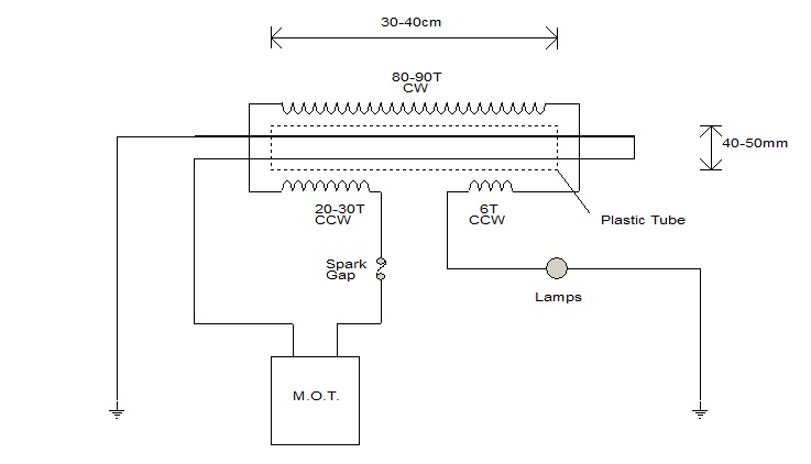
    It consists of an air core transformer with three windings, of which the two shorter windings are wound on top of the longer one, driven by a spark gap oscillator:


    As you see in the picture, there are three coils that are driven into resonance, where the shorter coils are wound counter clock wise(CCW), and the longer coil is wound clockwise(CW).

    Since the coil with 6 turns is the shortest one, that is the one where we have 1/4 lambda resonance, so if we would take the other short coil 3 x 6 = 18 turns, we would have 3/4 lambda over there. Now the 6 turn coil is a bit wider then the other one, so we would need a few more turns on the coil with the smaller diameter in order to get 3/4 lambda. For the long coil, we get 3 1/2 x 4 x 6 = 84 turns, which would be 1 1/2 lambda, so the terminals of the long coil would always be out of phase when the whole thing is in resonance.

    So far, so good.

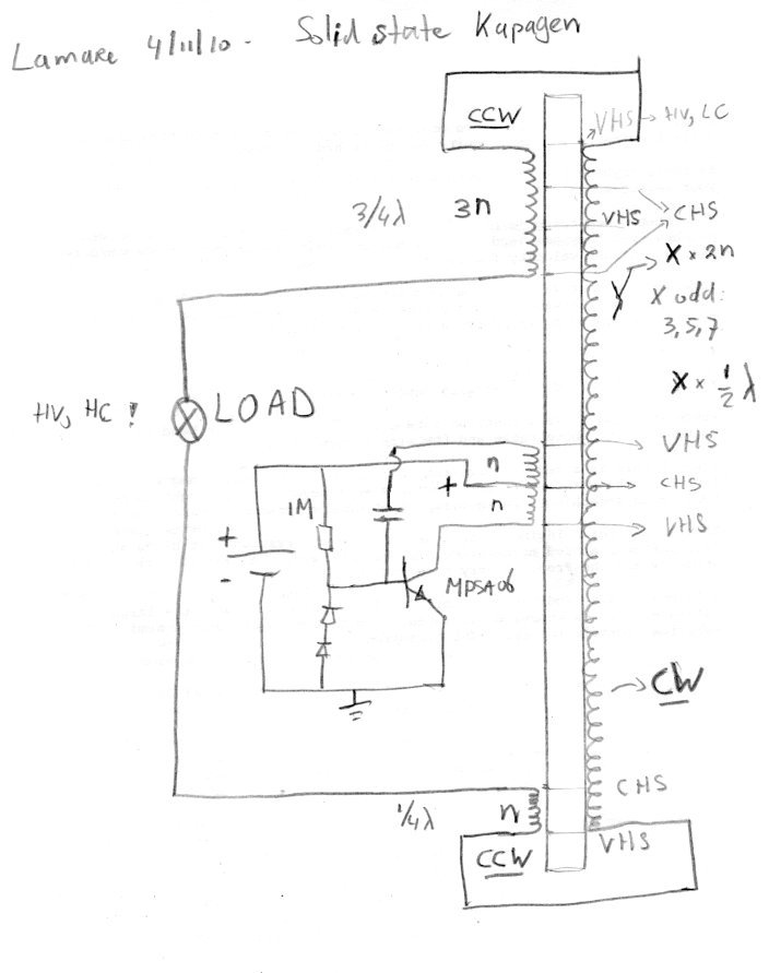
    Of course, it should also be possible to build the same kind of resonator using an exciter circuit, which could look like this:


    In this picture, the lower and upper coils are wound counter clock wise, wile the long coil is wound clockwise. The coils in the middle are the driving coils, which can be wound either way, as long as you wind them both in the same direction.

    The trick here is in matching the resonance frequencies and the voltage / current hot spots of the standing wave you get in the coil. Because the upper and lower coils are wound counter clock wise, where the outer terminals are connected to the outer terminals of the long coil, you force a current node (so a voltage hot spot) at the outer terminals of the long coil, when it is in resonance.

    However, you want to be able to draw current out of your coils, so you need to tap the power at a current hot spot (CHS), which is a 1/4 lambda along the way.

    So, when the lower coil is n turns, which determines the 1/4 lambda wavelength and the corresponding resonance frequency, at the top of this coil, you have a current hot spot. At the other end, you would also get a current hot spot 1/4 lambda down the road, but if the long coil is an odd multiple of 1/2 lambda, then your current would be out of phase. So, you go yet another 1/2 lambda further and make the top coil 3/4 lambda.

    Then you get an interesting situation. The current at the terminals of the upper (3/4) and lower (1/4) lamda coils are in phase, while there is a nice voltage across these terminals....

    I think for use with an exciter oscillator, as shown in the picture, you can wind the whole thing with the same diameter coil wire. Since you wind the shorter coils on top of the long one, the diameter will be slightly bigger, so you may need a few more turns on the long coil.

    I think it is important to place the driving/tickler coil such that the connection to the power supply is at a current hot spot. Since for every n turns we have a quarter lambda and the first current hot spot is at n turns above the bottom, the current hot spots will be at every 2n turns above this hot spot, so at every n + X*2n turns above the bottom turn of the long coil.

    And finally, the long coil should be an odd number times the half wave resonance frequency, so 3,5,7,... times 2n turns. The longer, the more voltage, so the better.

    Have fun if you try this!

    Update: Naudin references some very interesting papers on the advantages of bifilar wound coils in terms of voltage gain:

    Already this one is intriguing, it suggests that even with DC bifilar wound coils offer an advantage:
    Bifilar Electromagnet

    He also refers to some very interesting papers by Oliver Nichelson:
    teslanichelson

    http://home.comcast.net/~onichelson/VOLTGN.pdf
    [this] is a technical note showing that the equation for voltage gain will have to be modified for a special coil that may be related to Tesla's fuelless energy generator design. A regular coil and one of Tesla's design are measured and compared. Measurements show that the Tesla design is over 900% better in voltage gain than predicted by calculation.
    http://home.comcast.net/~onichelson/Thermodynamics2.pdf
    [this] was prepared for the 28th (1993) IECEC conference. It takes up Tesla's argument for a fuelless electric power generator that does not violate the Second Law of Thermodynamics. Though the device appears to supply power without fuel, it is not a perpetual motion machine. Tesla's explanation and a modern analysis is given of the device's operation. This paper presents a more satisfactory theory about the engineering aspects of the new generator than the 1991 IECEC paper.

    http://home.comcast.net/~onichelson/Fuelless.pdf
    [this] was prepared for the 26th Intersociety Energy Conversion Engineering Conference in August 1991. The paper documents that Nikola Tesla claimed to have built an electrical power generator that would not consume fuel, where in his writings the description of such a device is found, the theory of how a fuelless generator could be possible, and a suggestion as to how Tesla's new device might have operated. The paper moves from historical fact, the claims for such a generator in a letter hand written by Tesla, to speculation about the operating principles of the inventions. At the time of writing the paper, the historical material was certain, but the engineering explanation of how the new type of generator worked was speculation.
    Update 2:
    Tesla explains the difference between ordinary wound coils and bifilar wound ones in one of his patents:
    www.Magnetricity.com ...

    In this Patent, Nikola Tesla tells us that ...

    • A standard solenoidal-wound coil of 1000 turns with a potential of 100 volts across it will have a difference of 0.1 volt between turns.

    • A BIFILAR-wound coil of the same number of turns will have a potential of 50 volts between turns.

    In that the stored energy is a function of the square of the voltages, the energy in the BIFILAR Coil will be ...

    50 squared / .1 squared = 2500 / .01 = 250,000 times greater than the standard coil
    In Tesla's own words:
    I have found that in every coil there exists a certain relation between its self-induction and capacity that permits a current of given frequency and potential to pass through it with no other opposition than that of ohmic resistance, or, in other words, as though it possessed no self-induction. This is due to the mutual relations existing between the special character of the current and the self-induction and capacity of the coil, the latter quantity being just capable of neutralizing the self-induction for that frequency. It is well-known that the higher the frequency or potential difference of the current the smaller the capacity required to counteract the self-induction; hence, in any coil, however small the capacity, it may be sufficient for the purpose stated if the proper conditions in other respects be secured. In the ordinary coils the difference of potential between adjacent turns or spires is very small, so that while they are in a sense condensers, they possess but very small capacity and the relations between the two quantities, self-induction and capacity, are not such as under any ordinary conditions satisfy the requirements herein contemplated, because the capacity relatively to the self-induction is very small.

    In order to attain my object and to properly increase the capacity of any given coil, I wind it in such way as to secure a greater difference of potential between its adjacent turns or convolutions, and since the energy stored in the coil considering - the latter as a condenser, is proportionate to the square of the potential difference between its adjacent convolutions, it is evident that I may in this way secure by a proper disposition of these convolutions a greatly increased capacity for a given increase in potential difference between the turns.
    The principle is that there is a certain parasite capacitance between coil windings, which stores a certain amount of energy. By winding the coil bifilar, you get substantial bigger voltage differences between adjacent windings and therefore more energy is being stored in these parasite/self capacitances. Since the energy stored in a capacitor equals 1/2 C V^2 ( Energy Stored on a Capacitor ), this is a significant difference in the amount of energy that is being stored in the coils self capacitance. And since in resonance, this energy is being flipped back and forth between the capacitance (voltage) and the inductance (current, magnetic component) you get significantly stronger oscillations in there.

    Update 3: Oliver Nichelson's experiment suggest this only applies at the 1/2 lambda resonance frequency, cause if 19,1 MHz is the 3/4 lambda resonance frequency, we would get the 1/2 lambda at 19,1 * 2/3 = 12.73 MHz, which appears to match:

    teslanichelson


    Full scale image: http://sites.google.com/site/teslanichelson/Helix.jpg


    Update 4:

    And this gives an interesting link to Meyer's later coils, which were.... bifilar wound:

    Article:Free Electric Energy in Theory and Practice - PESWiki


    Update 6:

    What is interesting is to compare Tesla's bifilar wound coil from his patent with the top/bottom coils in the Kapagen device. As you can see, Tesla connected them in series, in order to get the voltage difference, while in the Kapagen device they are wound CW/CCW. So, with Tesla's coil, the voltage difference between adjacent windings is distributed across the coil, while with the Kapagen device, this increases from top (connected part) to bottom. Given that with the Kapagen device, we have different length short coils at the top and the bottom, this suggests that you probably may use this principle also at higher harmonics with the Kapagen way of winding and still get this voltage gain effect. You see, with Tesla's way of winding, you only get the situation that the magnetic field caused by the currents trough each half of the coil cancel each other out at the half wave resonance frequeny (over the whole coil), while with Kapagen's, they seem to always(?) cancel one another out, or at least at more than one higher harmonic.

    So, it seems that with Kapagen's way of winding, you can create a pure (longitudinal, "pressure-like") electric oscillation across the coil windings, without creating a magnetic field....


    Update 7: Some further analysis and re-thinking about a solid-state Kapanagen device here:
    http://www.energeticforum.com/146489-post1921.html
    Last edited by lamare; 07-04-2011, 12:37 PM.

    Leave a comment:


  • Jiffycoil
    replied
    Jiffy Puck

    Late last night I wound a single wire pancake coil 275 turns 28 AWG magnet wire. The primary is a pancake coil 8 turns AWG 12 stranded wire copper wire. The Slayer Exciter is a TIP41A and a 1K ohm resistor. The output is very good. I will post results soon.


    Jiffy Puck 1 by jiffycoil, on Flickr


    Jiffy Puck 2 by jiffycoil, on Flickr
    Last edited by Jiffycoil; 11-05-2010, 05:24 AM.

    Leave a comment:


  • penno64
    replied
    Hi all,

    Been rather busy of late.

    Did anyone else notice that when woopy attempted to combine the coils
    vertivcally, he got very little output.

    Does this seem familiar to the Steven Marks TPU that, would not work if
    it was inverted ??

    Any thouhgts ??

    Kindest Regards, Penno

    p.s. still trying to compress video for upload to youtube

    Leave a comment:


  • Jiffycoil
    replied
    New Bifilar Pancake coil

    This is the new coil. I used #23 and #26 AWG magnet wire. I wound this coil on a 1/2" white nylon tube purchased in the plumbing section of Home Depot. I used "Duck general purpose masking tape" .70 in x 55 yards bought at Wall mark .77 cents. I wound this on my homemade winding machine. I would 275 turns with the wire side by side. This gets a bit hard after around ten turns so you have to start crossing slightly side to side of the winding underneath. I ran this coil on the standard Bedini school girl circuit and with a 1/2 in neo mag sphere it is unreal and the voltage to charge is outstanding.


    Bifilar Pancake Coil Front Side by jiffycoil, on Flickr


    Bifilar Pancake Coil Front by jiffycoil, on Flickr

    Thanks for all the support here . I really enjoy my times with all of you.

    Leave a comment:


  • mk1
    replied
    I wonder why Tesla invented single wire tech , because he could replace the single wire with earth , i hope at least some one will show how far those circuit can send energy ...

    He said he could hit earth like a hammer , sending waves ...

    There is a part in the air , and one in the ground ...

    Mark

    Leave a comment:


  • Jiffycoil
    replied
    @Woopy
    Very nice job on your build and wonderful output too.

    Leave a comment:


  • woopy
    replied
    Hi all

    Thanks to all for contributing ,it really helps to go on understanding what is going on here.

    So i made some test today with Slayer and joulethief circuitery. And i have made a small vidêo to show with less words something very interesting with those pancake coils.

    Perhaps the pancake coil à la Ecoman will bring better results ? who knows ?

    And good experimenting

    Laurent

    YouTube - bifilar Tesla pancake wireless coupling.wmv

    Leave a comment:


  • lamare
    replied
    Originally posted by Lidmotor View Post
    @ Jiffycoil
    Your bifilar coil looks like another winner and I'll try that next. There is so much information on packcake coil design that it is kinda hard to filter through it all. Tesla sure did like these things.
    I did some analysis on coils some time ago, and found an interesting figure back then:

    http://www.energeticforum.com/renewa...html#post59469
    http://www.energeticforum.com/renewa...html#post59740

    I have always wondered what would be so special about a flat spiral and why Tesla would use such a coil. Now I realise you get an extreme h/d, nearing to 0. Now take a look at this figure, the base of an approximation to calculate the first TEM self-resonance frequency of a coil I posted before:


    What you see is that the velocity factor, the relative propagation speed with which EM electricity travels in/out of the coil, in the extreme nears to 0 also!

    Very interesting!

    What you have with a flat, spiral coil, is minimal capacitive coupling, while still having a considerable inductive coupling between the windings.
    Today, I would think it's the other way around and that with a pancake coil you mostly have capacitive coupling and hardly any magnetic component, especially if you use higher harmonic resonances as you do with these kind of circuits, because your driving coil (together with the feedback coil) is the one that determines the oscillation frequency to a large degree and that one is usually much shorter than high voltage coil and thus has a (much) higher resonance frequency.

    Update 3: note that Tesla used bifilar wound pancake coils also:
    Tesla Bifilar Coil patent - Bedini Bifilar Coil usage in Schoolgirl Radiant Motor Charging devices | MERLib.org

    Tesla explains that a standard coil of 1000 turns with a potential of 100 volts across it will have a difference of .1 volt between turns. A similar bifilar coil will have a potential of 50 volts between turns. In that the stored energy is a function of the square of the voltages, the energy in the bifilar will be 502/.12 = 2500/.01 = 250,000 times greater than the standard coil!"
    Practical Guide to Free-Energy Devices - Chapter 9
    May I also remark that it might be worth experimenting with the “pancake” coil (called a bi-filar series-connected coil) patented by Tesla because he found that it was particularly effective in picking up Zero-Point Energy:

    Update: I suddenly wonder what would happen if you would go to 3D coils, i.e. wind them like your grandmother would wind a ball of wool:


    Then you would have one terminal in the centre of a ball-like structure, which spirals out in 3D towards the outside.... Of course, you can wind this with an inner bal, surrounded with an outer one...

    Update 2:

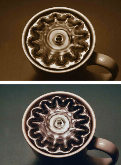
    If indeed capacitive coupling is the dominant coupling mechanism, we would be talking about electric waves propagating from one winding to the next, which would be akin to pressure waves in a fluid, which would have an interesting analogy with acoustics. With acoustic pressure waves, one can make interesting pressure wave patterns, which would be similar to what would happen inside a resonating pancake coil. This is known as cymatics:

    Cymatics

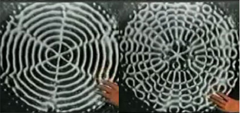
    This is a 2D pattern:

    A simple experiment demonstrating the visualization of cymatics can be done by sprinkling sand on a metal plate and vibrating the plate, for example by drawing a violin bow along the edge, the sand will then form itself into standing wave patterns such as simple concentric circles. The higher the frequency, the more complex the shapes produced, with certain shapes having similarities to traditional mandala designs.
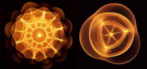
    In 3D, we get similar patterns:


    The left half of the images show the same kind of pattern, one in 2D, one in 3D. As you can see, you get a hot spot in the centre, so it may be possible to do something similar with 3D ball / wool knot shaped coils.

    Update 4: There's an interesting post on this velocity factor and standing waves here:
    http://www.energeticforum.com/renewa...html#post37830

    The referenced article, link dead, can be retrieved from the internet archive:
    Class Notes: Tesla Coils and the Failure of Lumped-Element Circuit Theory

    Very interesting:
    However, a true Tesla coil (circa 1894) is a velocity inhibited slow-wave helical transmission line resonator: Vmax = S×Vmin, where S is the standing wave ratio. Voltage magnification is by standing waves. Period.
    Update 5: There's a very interesting site about Tesla coils here: Tesla Secondary Simulation Project

    Update 6: Found a very interesting paper by the same Corum who wrote the Class Notes: "Voltage Magnification by Standing Waves" http://hamwaves.com/antennas/inductance/corum.pdf


    Update 7: One more picture on cymatics:
    Cymatics : Physics • Rational Skepticism Forum


    I like these kinds of images, because I believe there is a real ether, as Tesla always said, so these cymatic techniques enable us to make pictures and video's of how waves propagate trough the medium, be it water or the ether.
    Last edited by lamare; 11-04-2010, 08:45 AM. Reason: moved cymatic images to my own server; added wool ball picture

    Leave a comment:

Working...
X