Announcement

Collapse
No announcement yet.

Joulethief SEC exciter and variants

Collapse
X
 
  • Filter
  • Time
  • Show
Clear All
new posts

  • Originally posted by xee2 View Post
    If you want to increase the collector curent just reduce the value of the resistor.
    Reducing the base resistance also reduces the frequency. I'm pretty sure these things are more efficient at higher frequencies.

    DC to DC Boost circuit?

    Comment


    • Jiffycoil's " Pancake coil Exciter"

      Originally posted by Jiffycoil View Post
      I thought I would test the new setup and see how far I can transmit energy by single wire.

      YouTube - Single Wire Pancake
      @Jiffy and All
      I replicated your "Pancake coil Exciter" today and was amazed at how well it worked. . I just hand wound the coil and in less than an hour it was up and running. You are right about there not being hardly any energy field around it though. That is not really a bad thing if all you are trying to do is one wire energy transmission. The light /watt (bang for the buck) is great.
      Here is a video of my Happy Halloween build:

      YouTube - Jiffycoil's Pancake coil Exciter.ASF

      Lidmotor

      Comment


      • double pancake exciter

        Hi Jiffycoil and Lidmotor

        Thanks for sharing your great work

        And ofcourse i tried to replicate the pancake coil.

        It is really easy to do.

        It works well but i do not get the terriffic result of Jiffy.

        My coil has 2,5 Ohm and 0.4 mh for about 70 turns of 0.4 mm copper (about 26 AWG). What is your coil ?

        I tried all my transistors and all work from 2N222A to Tip 31c and also a FET.

        After trying different L2 winding, i decided to test a L2 in pancake form and it seems to work better than with the outer L2 coil. When i press the L2 pancake on the L1 , the current goes down, I think a good idea would be to make a flatter L1 pancake , so the L2 will be more near the L1 winding. May be.
        Will go on the test.

        Hopes this helps

        Good Halloween at all

        Laurent
        Last edited by woopy; 05-16-2011, 09:34 PM.

        Comment


        • Originally posted by Jiffycoil View Post
          @Lamare
          I just read through your paper and your idea of driving to identical power transformers in resonance is very interesting. I would love to try this. I really enjoyed your paper by the way.
          I made some Spice simulations on how to do this:
          Index of /Spice

          The "basic" circuit is how you could actually do this:


          The 2_Identical_TF circuit is the same circuit with parasite components, etc. for the Spice simulation. You may have to add a trimmer across L1 and L2 as done in the canary circuit to tune the resonance frequency of the primaries to a higher harmonic of the secondary.

          In principle, this is about the same driving circuit as Slayers. The major difference is the separate tickler/feedback coil L2, for which Slayer uses L3. If you make them separate coils, you can connect both terminals of the secondary coil to the transformer you want to drive.

          So, you can do this with either Slayer kinds of air core coils, which will most likely work. I guess it will also work with iron core transformers, but I'm not sure.

          Anyway, if this works, this may be a way to close the loop and create a self-running system.

          Please be aware that I haven't actually built this, but at least the circuit should oscillate as shown in the simulator, even though you may have to use a bigger couple cap, depending on the oscillation frequency of the actual transformer. So, have fun if you try this!

          If you want to try this with power transformers, a 220V - 2x12V may be a good start, because 220/16 = 13.75, which would mean that for a transformer from 220 to 13.75 one could fit exactly 4 times the quarter wave resonance frequency of the primary in the secondary, assuming you have the same parasite capacitance per winding. For 12V the coil is a bit shorter, so a bit higher resonance frequency, which can be corrected using a trimmer across L1 and L2.
          Last edited by lamare; 11-01-2010, 06:16 PM.

          Comment


          • Originally posted by lamare View Post
            I made some Spice simulations on how to do this:
            Index of /Spice

            The "basic" circuit is how you could actually do this:


            The 2_Identical_TF circuit is the same circuit with parasite components, etc. for the Spice simulation. You may have to add a trimmer across L1 and L2 as done in the canary circuit to tune the resonance frequency of the primaries to a higher harmonic of the secondary.

            In principle, this is about the same driving circuit as Slayers. The major difference is the separate tickler/feedback coil L2, for which Slayer uses L3. If you make them separate coils, you can connect both terminals of the secondary coil to the transformer you want to drive.

            So, you can do this with either Slayer kinds of air core coils, which will most likely work. I guess it will also work with iron core transformers, but I'm not sure.

            Anyway, if this works, this may be a way to close the loop and create a self-running system.

            Please be aware that I haven't actually built this, but at least the circuit should oscillate as shown in the simulator, even though you may have to use a bigger couple cap, depending on the oscillation frequency of the actual transformer. So, have fun if you try this!

            If you want to try this with power transformers, a 220V - 2x12V may be a good start, because 220/16 = 13.75, which would mean that for a transformer from 220 to 13.75 one could fit exactly 4 times the quarter wave resonance frequency of the primary in the secondary, assuming you have the same parasite capacitance per winding. For 12V the coil is a bit shorter, so a bit higher resonance frequency, which can be corrected using a trimmer across L1 and L2.
            *lamare
            So you are saying that your Spice simulations are showing the so called 'Slayer' circuit and the one shown here as over unity? Strange as the Spice engine is written with conventional formula which will not present OU??

            You might want to run you simulations for a longer period of time. Micro-Cap will easily show OU if the time over which the sim is run is short.

            DC.

            Comment


            • Originally posted by conradphd View Post
              *lamare
              So you are saying that your Spice simulations are showing the so called 'Slayer' circuit and the one shown here as over unity? Strange as the Spice engine is written with conventional formula which will not present OU??

              You might want to run you simulations for a longer period of time. Micro-Cap will easily show OU if the time over which the sim is run is short.

              DC.
              No, I'm saying the simulator shows it's oscillating and it gives you some insight in how the currents are flowing trough the circuit, even within the coils themselves if you split them into multiple sub-coils in series. I'm pretty sure it won't show OU, because the engine does use conventional formula indeed, which consider the electric field to be a static force, while in actual fact it is a dynamic force. It is exactly that difference that enables you to build OU devices, as Tesla said more than a hundred years ago:

              "Experiments with Alternate Currents of High Potential and High Frequency"

              Throughout space there is energy. Is this energy static or kinetic! If static our hopes are in vain; if kinetic—and this we know it is, for certain—then it is a mere question of time when men will succeed in attaching their machinery to the very wheelwork of nature.
              So, a simulation can be useful to design your (oscillator) circuit. With my ideas, it made very clear that driving a transformer trough an AV plug (half diode bridge) shorts the transformers out in the second half of the oscillation. So, it is helpful for gaining insight, even though it definitely has it's limits.

              The simulation of the Slayer/Stiffler circuit gives pretty interesting results when you FFT (spectrum analyse) the currents/voltages in the circuit:

              Article:Free Electric Energy in Theory and Practice - PESWiki


              These show the same kind of wide-band spectrum Dr. Stiffler shows with the actual circuit and are caused by the strong feedback circuit that is being used. This causes higher harmonic oscillations to occur, which I think is benefitial in circuits that aim to achieve OU, because with higher harmonics the currents are more localized inside the coils and you only have to drive one node of the wave inside the coils yourself.

              Anyway, you can easily play with that in the simulator and see what happens when you change the feedback circuit, for example by exchanging the diode(s) with a resistor and/or place a capacitor in parallel with the diode(s) at the base of the transistor. You can also see the difference between transistors. For example, the 2N3055 won't fly with this stuff....
              Last edited by lamare; 11-01-2010, 08:51 PM.

              Comment


              • Originally posted by lamare View Post
                No, I'm saying the simulator shows it's oscillating and it gives you some insight in how the currents are flowing trough the circuit, even within the coils themselves if you split them into multiple sub-coils in series. I'm pretty sure it won't show OU, because the engine does use conventional formula indeed, which consider the electric field to be a static force, while in actual fact it is a dynamic force. It is exactly that difference that enables you to build OU devices, as Tesla said more than a hundred years ago:

                "Experiments with Alternate Currents of High Potential and High Frequency"


                So, a simulation can be useful to design your (oscillator) circuit. With my ideas, it made very clear that driving a transformer trough an AV plug (half diode bridge) shorts the transformers out in the second half of the oscillation. So, it is helpful for gaining insight, even though it definitely has it's limits.

                The simulation of the Slayer/Stiffler circuit gives pretty interesting results when you FFT (spectrum analyse) the currents/voltages in the circuit:

                Article:Free Electric Energy in Theory and Practice - PESWiki


                These show the same kind of wide-band spectrum Dr. Stiffler shows with the actual circuit and are caused by the strong feedback circuit that is being used. This causes higher harmonic oscillations to occur, which I think is benefitial in circuits that aim to achieve OU, because with higher harmonics the currents are more localized inside the coils and you only have to drive one node of the wave inside the coils yourself.

                Anyway, you can easily play with that in the simulator and see what happens when you change the feedback circuit, for example by exchanging the diode(s) with a resistor and/or place a capacitor in parallel with the diode(s) at the base of the transistor. You can also see the difference between transistors. For example, the 2N3055 won't fly with this stuff....
                *lamare
                Along with Dr. Stiffler I think we have run well into a thousand simulations using both Spice and Micro-Cap so I fully understand the utility of simulations. Considering a connection to the energy lattice to be similar to opening a door and the amount of energy flow depends on how open the door is; determines excess feedback energy.

                Most of the circuits we see here are free running with uncontrolled feedback and dissipation. It appears feedback is dumped via diodes and transistors are driven into heavy saturation. with the door only open a crack one will never be able to determine recovery without calorimetry.

                You circuit as shown looks nice but does not work as expected in the real world.

                DC

                (edit)
                Please look at the following link for something simple and interesting.
                JLN Labs - The Time Energy Pump V2.1
                Last edited by conradphd; 11-01-2010, 09:51 PM.

                Comment


                • Originally posted by lamare View Post
                  I made some Spice simulations on how to do this:
                  Index of /Spice

                  The "basic" circuit is how you could actually do this:


                  The 2_Identical_TF circuit is the same circuit with parasite components, etc. for the Spice simulation. You may have to add a trimmer across L1 and L2 as done in the canary circuit to tune the resonance frequency of the primaries to a higher harmonic of the secondary.

                  In principle, this is about the same driving circuit as Slayers. The major difference is the separate tickler/feedback coil L2, for which Slayer uses L3. If you make them separate coils, you can connect both terminals of the secondary coil to the transformer you want to drive.

                  So, you can do this with either Slayer kinds of air core coils, which will most likely work. I guess it will also work with iron core transformers, but I'm not sure.

                  Anyway, if this works, this may be a way to close the loop and create a self-running system.

                  Please be aware that I haven't actually built this, but at least the circuit should oscillate as shown in the simulator, even though you may have to use a bigger couple cap, depending on the oscillation frequency of the actual transformer. So, have fun if you try this!

                  If you want to try this with power transformers, a 220V - 2x12V may be a good start, because 220/16 = 13.75, which would mean that for a transformer from 220 to 13.75 one could fit exactly 4 times the quarter wave resonance frequency of the primary in the secondary, assuming you have the same parasite capacitance per winding. For 12V the coil is a bit shorter, so a bit higher resonance frequency, which can be corrected using a trimmer across L1 and L2.
                  @lamare
                  I am having a bit of trouble understand this circuit. You show a voltage source V1 feeding through a diode to Vcc. Now if V1<Vcc it serves no purpose. If V1> Vcc then why have Vcc??

                  Your coils off the transistor collector are far from balanced, the effect you are really looking for can not result because of this imbalance. Have not moved farther as this is a stump-er indeed.

                  EDIT:
                  Conrad told me you must be indicating a connector with the Vcc naming so I'll accept that, yet why the diode, waste of heat and the large cap has a pretty high impedance, maybe add a 0.1uf and a 0.01uf (not the cheap kind) to insure no feed back into the supply. Actually a bead or two placed properly would help.

                  So if I read this right the cores of the two xformers are not mutually connected?
                  Last edited by DrStiffler; 11-01-2010, 10:26 PM.

                  Comment


                  • hi to the pancake Jiffycoil replicators

                    I have spoken with some determination to my L1 pancake coil and she accepted to make some effort to get thinner.
                    And she was right the results is very good.

                    For info after some quick testing ,for tonight I got my best result with the transistor 2N 3904 at 5 volts.

                    good night at all

                    Laurent
                    Last edited by woopy; 01-26-2011, 10:47 AM.

                    Comment


                    • Sometimes a kind word with determination does the trick. Cheers I look forward to your results.

                      Comment


                      • Well done everyone working on the jiffycoil pancake reps! I like the way ideas come fast and furious in this thread

                        I've been working with my ion motors and ground. The first minute of the vid shows 2 ion motors - one is connected to the output of the coil, but the other is connected ONLY to ground. I noticed that a ground wire near an exciter will also produce a plasma jet, so I hung one ion motor in the centre of the secondary coil only connected to ground, and it worked just as well as the output wire connection. In fact, they easily work at the same time. In the last few seconds of the vid, I show 3 ion motors running simultaneously. They are all connected to the output wire, but they hang close to my toroid which is connected to ground. The proximity of ground seems to accelerate the motors.
                        Input is 15V @ 1A.

                        I also show an AV plug lighting an LED far from the exciter - I can do this round the house even on 1AA in a charger.

                        YouTube - exciter ion motor 5 (Music not permitted )

                        I wanna get my exciter running on an earth battery, or something else that wont stop providing power for a long time (Peltier module/radiant energy collector/atospheric generator). Lids solar powered exciter and pirates J.thief always impressed me - practical solutions for low power permanent lighting. I know there are others here who have also managed similar feats. Well done to all! Adn like always, good luck!

                        Comment


                        • Originally posted by seth View Post
                          Well done everyone working on the jiffycoil pancake reps! I like the way ideas come fast and furious in this thread

                          I've been working with my ion motors and ground. The first minute of the vid shows 2 ion motors - one is connected to the output of the coil, but the other is connected ONLY to ground. I noticed that a ground wire near an exciter will also produce a plasma jet, so I hung one ion motor in the centre of the secondary coil only connected to ground, and it worked just as well as the output wire connection. In fact, they easily work at the same time. In the last few seconds of the vid, I show 3 ion motors running simultaneously. They are all connected to the output wire, but they hang close to my toroid which is connected to ground. The proximity of ground seems to accelerate the motors.
                          Input is 15V @ 1A.

                          I also show an AV plug lighting an LED far from the exciter - I can do this round the house even on 1AA in a charger.

                          YouTube - exciter ion motor 5 (Music not permitted )

                          I wanna get my exciter running on an earth battery, or something else that wont stop providing power for a long time (Peltier module/radiant energy collector/atospheric generator). Lids solar powered exciter and pirates J.thief always impressed me - practical solutions for low power permanent lighting. I know there are others here who have also managed similar feats. Well done to all! Adn like always, good luck!
                          I manage to "start" my slayer exciter, only by using a 100uF cap instead of the battery and a AV plug with the (-)side connected to the ground and the + side to a sheet of double copper board(13cmx21cm), the led was not light super bright, but was enough light to read a postcard at night .
                          The only problem was that my exciter didn't work "on wireless", the AV plug only worked when connected to L1 output (no wireless light around the LI coil)

                          Comment


                          • Originally posted by DrStiffler View Post
                            @lamare
                            I am having a bit of trouble understand this circuit. You show a voltage source V1 feeding through a diode to Vcc. Now if V1<Vcc it serves no purpose. If V1> Vcc then why have Vcc??

                            Your coils off the transistor collector are far from balanced, the effect you are really looking for can not result because of this imbalance. Have not moved farther as this is a stump-er indeed.

                            EDIT:
                            Conrad told me you must be indicating a connector with the Vcc naming so I'll accept that, yet why the diode, waste of heat and the large cap has a pretty high impedance, maybe add a 0.1uf and a 0.01uf (not the cheap kind) to insure no feed back into the supply. Actually a bead or two placed properly would help.
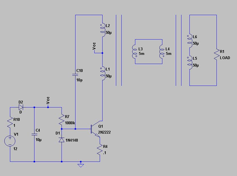
                            Those were some remnants of the simulator version. It is handy to do it like that in the simulator, because then you can easily "measure" the DC current being drawn. Here's an updated picture:


                            So if I read this right the cores of the two xformers are not mutually connected?
                            That is an interesting question. How important is the magnetic coupling anyway when you are using higher harmonic resonance in your coil? And, does a core actually help when using higher harmonic resonance?

                            I have done some analysis on resonating coils some time ago, considering both the longitudinal and transverse components of the waves traveling along the coils:

                            Article:Free Electric Energy in Theory and Practice - PESWiki

                            Conclusion: The longitudinal component of the wave across coil windings has the magnetic field component H in parallel with the wire, while the current moves perpendicular to the coil wire, across the surface. In order words: when f goes to infinity, the external supplied current goes to zero.
                            When you have multiple nodes of a standing wave in your coil, there are distinct areas where the magnetic components are out of phase, so I suspect the (longitudinal) electric component becomes dominant pretty quickly and that the actual coupling between the coils/sections is much more electro"static" than magnetic in nature.

                            So, normal power transformers where you have two separate coils which are magnetically coupled trough the core probably won't fly when using higher harmonic resonances. A toroid which has the coils wound on top of one another may work. However, HF air core coils, as in the exciter circuits, are the most promising ones.

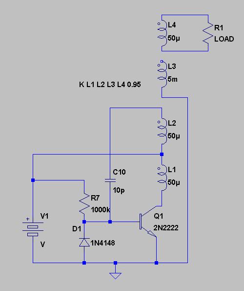
                            I am beginning to think that all we need is just one more winding at the top of the coil, with either the same number of turns as the driving coil, or a multiple thereof. (Update: the top winding needs at least twice the number of turns as the driving coil, since the driving coil + the tickler coil form one half wave resonator together. So the top coil needs to be that side. See post further down.) Since you have a strong electric field at the top of the resonating coil, and the dominant energy transfer mechanism would be the electric field, then you should be able to excite a pickup coil at the top of the long coil easily, so you can tap the power there:


                            It should be easy to use a bridge rectifier as load to charge a capacitor...

                            Update: note that the values for the coils are just guesstimates and that you probably want to go for the MPSA06 as the transistor. I used the 2N2222 in the simulator, cause the MPSA06 is not standard included with LTSpice.

                            @Doc: Coming to think of it, IIRC, the 2N2309 gives comparable results in terms of bandwidth as the MPSA06 in the simulator, so that may be a possible alternative to the MPSA06 should that one become unavailable, even though it can only handle 200 milliAmp. You can see the difference in the spectra from the simulation of http://www.tuks.nl/Spice/StifflerSlayer.asc with the 2N2222 and the 2N2309 in the attached image. Unfortunately, at this PC I don't have a Spice model for the MPSA06 for comparison.

                            Found one: http://www.onsemi.com/pub_link/Collateral/MPSA06.LIB - simply add the contents of this file to the "standard.bjt" file in lib\cmp. See the comparison of the spectra for the MPSA06, the 2N3904 and the 2N2222 in the second attached file. Some further simulations suggest the bc337-40 (http://www.datasheetcatalog.org/data...a/BC338-16.pdf) may also be a possible alternative for the MPSA06. This one can handle 800 milliAmps.

                            Update: looks like I made a typo. I meant 2N3904 not 2N2309...
                            Attached Files
                            Last edited by lamare; 11-02-2010, 04:04 PM.

                            Comment


                            • Originally posted by lamare View Post
                              Those were some remnants of the simulator version. It is handy to do it like that in the simulator, because then you can easily "measure" the DC current being drawn. Here's an updated picture:


                              That is an interesting question. How important is the magnetic coupling anyway when you are using higher harmonic resonance in your coil? And, does a core actually help when using higher harmonic resonance?

                              I have done some analysis on resonating coils some time ago, considering both the longitudinal and transverse components of the waves traveling along the coils:

                              Article:Free Electric Energy in Theory and Practice - PESWiki


                              When you have multiple nodes of a standing wave in your coil, there are distinct areas where the magnetic components are out of phase, so I suspect the (longitudinal) electric component becomes dominant pretty quickly and that the actual coupling between the coils/sections is much more electro"static" than magnetic in nature.

                              So, normal power transformers where you have two separate coils which are magnetically coupled trough the core probably won't fly when using higher harmonic resonances. A toroid which has the coils wound on top of one another may work. However, HF air core coils, as in the exciter circuits, are the most promising ones.

                              I am beginning to think that all we need is just one more winding at the top of the coil, with either the same number of turns as the driving coil, or a multiple thereof. Since you have a strong electric field at the top of the resonating coil, and the dominant energy transfer mechanism would be the electric field, then you should be able to excite a pickup coil at the top of the long coil easily, so you can tap the power there:


                              It should be easy to use a bridge rectifier as load to charge a capacitor...

                              Update: note that the values for the coils are just guesstimates and that you probably want to go for the MPSA06 as the transistor. I used the 2N2222 in the simulator, cause the MPSA06 is not standard included with LTSpice.

                              @Doc: Coming to think of it, IIRC, the 2N2309 gives comparable results in terms of bandwidth as the MPSA06 in the simulator, so that may be a possible alternative to the MPSA06 should that one become unavailable, even though it can only handle 200 milliAmp. You can see the difference in the spectra from the simulation of http://www.tuks.nl/Spice/StifflerSlayer.asc with the 2N2222 and the 2N2309 in the attached image. Unfortunately, at this PC I don't have a Spice model for the MPSA06 for comparison.

                              Found one: http://www.onsemi.com/pub_link/Collateral/MPSA06.LIB - simply add the contents of this file to the "standard.bjt" file in lib\cmp. See the comparison of the spectra for the MPSA06, the 2N3904 and the 2N2222 in the second attached file. Some further simulations suggest the bc337-40 (http://www.datasheetcatalog.org/data...a/BC338-16.pdf) may also be a possible alternative for the MPSA06. This one can handle 800 milliAmps.
                              @lamare
                              That is an interesting question. How important is the magnetic coupling anyway when you are using higher harmonic resonance in your coil? And, does a core actually help when using higher harmonic resonance?
                              Depending on the frequency the core can defeat the desired goal, of course. Now for a simulation and what value to use for Mu when using an air core. Mu is not a fixed value in air cores and has a substantial range. One finds that in moving from one extreme to the next that it is not practical to assume a fixed value.

                              @Doc: Coming to think of it, IIRC, the 2N2309 gives comparable results in terms of bandwidth as the MPSA06 in the simulator
                              I would heavily dispute the result, look at it with an SA and you would see the difference between sims and actual circuits.

                              I fail to understand ow you are accounting for the negative resistance effect of the MPSA06? As seen in an authentic SEC Exciter the Vce breakdown is playing a significant part in the operation. In an authentic SEC Exciter the utilization of the two 1N4148's and the White LED serve a purpose of limiting the negative spike to ~0.7+0.7+3.6. Whereas in the slayer circuits it is used to prevent blowing the transistor from excessive feedback. Where a double set of diodes are used in reverse configuration in a slayer exciter, the operational bandwidth is greatly reduced and the diode in the same polarity as the BE junction serve little practical purpose as the Vbe is the controlling breakdown potential, they do although not shown in any sim act as a small varicap when reverse biased, yet this is very small and only of value at UWB frequencies.

                              The feedback coil is way to big and much energy is pumped into the environmental capacity as a result, this is why replicators of slayer are seeing action from both L2 and L3, yet the sole purpose should be the load coil and not the feedback coil. Additionally the small base resistors in the slayer exciter are a total waste of energy and I see in your circuit that you use an acceptable value. Similar to (Vbb-Vbe)/Rb

                              Now might I ask the question of what the difference is in taking the energy from the ground rail as opposed to the collector coil, same thing is it not (unless this is actual an earth ground) ?

                              What you are trying to do can not be simulated, sadly it don't work the way the results show.

                              Anyway good luck to all, BTW the 2013 SEC Circuit has passed Beta with flying colors.

                              Comment


                              • Originally posted by DrStiffler View Post
                                The feedback coil is way to big and much energy is pumped into the environmental capacity as a result, this is why replicators of slayer are seeing action from both L2 and L3, yet the sole purpose should be the load coil and not the feedback coil. Additionally the small base resistors in the slayer exciter are a total waste of energy and I see in your circuit that you use an acceptable value. Similar to (Vbb-Vbe)/Rb
                                It has to be this size, otherwise you won't get a 180 degree phase shift in the feedback loop, which is required to keep the oscillation going at the right frequency.


                                Now might I ask the question of what the difference is in taking the energy from the ground rail as opposed to the collector coil, same thing is it not (unless this is actual an earth ground) ?

                                What you are trying to do can not be simulated, sadly it don't work the way the results show.

                                Anyway good luck to all, BTW the 2013 SEC Circuit has passed Beta with flying colors.

                                According to a.o. Eric Dollard, it is the electric field that induces currents inside your wires or your coils, which is not a static force, as we usually consider it to be. Since the electric field actually resides outside your coil wires (since conductors oppose an electric field) and the electric field is an energy source, as shown by Prof. Turtur, you can pick up oscillations of the electric field for free, as far as I understand.

                                If that is correct and it is also correct that the dominant coupling mechanism in coils resonating at higher harmonics is the electric field, then you could use a strong electric field to bring a coil into resonance, while the magnetic coupling would play a less significant role.

                                Given that with an oscillator with a tickler coil, the driving and tickler coil together act as a half wave resonator, you can drive another half wave resonator using high voltage, zero current by means of coupling trough the electric field.

                                I changed the schematic a bit (see attachment), so that the top coil is twice the amount of windings as the individual driver/ticker coils, and the upper terminal is connected to ground.

                                Since there is high voltage at the long, resonating coil, that should do to drive the upper coil into resonance, only using a much stronger electric field compared to the fields that are present at the bottom part.

                                And if all this is correct, that should give interesting results...
                                Attached Files
                                Last edited by lamare; 11-02-2010, 06:40 PM. Reason: Corrected an error: no electric field inside conductors.

                                Comment

                                Working...
                                X